
User's Manual


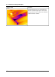


Table Of Contents
- Table of contents
- 1 Warnings & Cautions
- 2 Notice to user
- 3 Customer help
- 4 Documentation updates
- 5 Important note about this manual
- 6 Parts lists
- 7 Quick Start Guide
- 8 Camera parts
- 9 Screen elements
- 10 Navigating the menu system
- 11 Connecting external devices and storage media
- 12 Pairing Bluetooth devices
- 13 Configuring Wi-Fi
- 14 Handling the camera
- 15 Working with images
- 16 Working with thermal fusion and picture-in-picture image modes
- 17 Working with measurement tools
- 18 Fetching data from external Extech meters
- 19 Working with isotherms
- 20 Annotating images
- 21 Recording video clips
- 22 Changing settings
- 23 Cleaning the camera
- 24 Technical data
- 25 Dimensional drawings
- 25.1 Camera dimensions, front view (1)
- 25.2 Camera dimensions, front view (2)
- 25.3 Camera dimensions, side view (1)
- 25.4 Camera dimensions, side view (2)
- 25.5 Camera dimensions, side view (3)
- 25.6 Infrared lens (30 mm/15°)
- 25.7 Infrared lens (10 mm/45°)
- 25.8 Battery (1)
- 25.9 Battery (2)
- 25.10 Battery (3)
- 25.11 Battery charger (1)
- 25.12 Battery charger (2)
- 25.13 Battery charger (3)
- 25.14 Battery charger (4)
- 26 Application examples
- 27 Introduction to building thermography
- 27.1 Disclaimer
- 27.2 Important note
- 27.3 Typical field investigations
- 27.3.1 Guidelines
- 27.3.2 About moisture detection
- 27.3.3 Moisture detection (1): Low-slope commercial roofs
- 27.3.4 Moisture detection (2): Commercial & residential façades
- 27.3.5 Moisture detection (3): Decks & balconies
- 27.3.6 Moisture detection (4): Plumbing breaks & leaks
- 27.3.7 Air infiltration
- 27.3.8 Insulation deficiencies
- 27.4 Theory of building science
- 27.4.1 General information
- 27.4.2 The effects of testing and checking
- 27.4.3 Sources of disruption in thermography
- 27.4.4 Surface temperature and air leaks
- 27.4.5 Measuring conditions & measuring season
- 27.4.6 Interpretation of infrared images
- 27.4.7 Humidity & dew point
- 27.4.8 Excerpt from Technical Note ‘Assessing thermal bridging and insulation continuity’ (UK example)
- 28 Introduction to thermographic inspections of electrical installations
- 28.1 Important note
- 28.2 General information
- 28.3 Measurement technique for thermographic inspection of electrical installations
- 28.4 Reporting
- 28.5 Different types of hot spots in electrical installations
- 28.6 Disturbance factors at thermographic inspection of electrical installations
- 28.7 Practical advice for the thermographer
- 29 About FLIR Systems
- 30 Glossary
- 31 Thermographic measurement techniques
- 32 History of infrared technology
- 33 Theory of thermography
- 34 The measurement formula
- 35 Emissivity tables

27.3.7 Air infiltration
27.3.7.1 General information
Due to the wind pressure on a building, temperature differences between the inside
and the outside of the building, and the fact that most buildings use exhaust air terminal
devices to extract used air from the building, a negative pressure of 2–5 Pa can be
expected. When this negative pressure leads to cold air entering the building structure
due to deficiencies in building insulation and/or building sealing, we have what is
called air infiltration. Air infiltration can be expected at joints and seams in the building
structure.
Due to the fact that air infiltration creates an air flow of cool air into e.g. a room, it can
lead to substantial deterioration of the indoor climate. Air flows as small as 0.15 m/s
(0.49 ft./s) are usually noticed by inhabitants, although these air flows may be difficult
to detect using ordinary measurement devices.
On an infrared image air infiltration can be identified by its typical ray pattern, which
emanates from the point of exit in the building structure—e.g. from behind a skirting
strip. Furthermore, areas of air infiltration typically have a lower detected temperature
than areas where there is only an insulation deficiency. This is due to the chill factor
of the air flow.
27.3.7.2 Commented building structures
This section includes a few typical examples of details of building structures where
air infiltration may occur.
CommentStructural drawing
Insulation deficiencies at the eaves of a brickwall
house due to improperly installed fiberglass insu-
lation batts.
The air infiltration enters the room from behind the
cornice.
10552503;a2
100 Publ. No. T559597 Rev. a554 – ENGLISH (EN) – September 27, 2011
27 – Introduction to building thermography