
User Manual
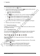
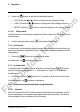

Table Of Contents
- 1 Disclaimers
- 2 Safety information
- 3 Introduction
- 4 Description
- 5 Operation
- 5.1 Powering the meter
- 5.2 Auto/Manual select mode
- 5.3 Auto/Manual range mode
- 5.4 Voltage measurements
- 5.5 Resistance measurements
- 5.6 Continuity test
- 5.7 Diode test
- 5.8 Capacitance measurements
- 5.9 Type K temperature measurements
- 5.10 Current measurements
- 5.11 Extended functionality
- 5.12 Hold mode
- 5.13 Locked mode
- 5.14 Streaming measurement data using Bluetooth
- 6 Maintenance
- 7 Technical specifications
- 8 Flir Global Limited Lifetime Warranty

5 Operation
3. Insert the black probe lead into the negative terminal and the red probe
lead into the positive
terminal.
4. Touch the tips of the probe across the part under test.
5. Read the capacitance value on the display.
Note
For very large capacitance values, it may take several minutes for the
measurement to settle and the final reading to stabilize.
5.9 Type K temperature measurements
1. Set the function switch to the
position.
2. Use the
button to select temperature measurement. The °F or °C unit
will be displayed.
3. While observing the polarity, insert the thermocouple adapter into the nega-
tive
terminal and the positive terminal.
4. Touch the tip of the thermocouple to the part under test. Keep the thermo-
couple tip on the part until the reading on the display stabilizes.
5. Read the temperature value on the display.
6. To avoid electrical shock, disconnect the thermocouple adapter before turn-
ing the function switch to another position.
5.10 Current measurements
Current is measured by disconnecting the part under test and connecting the
probe leads in series with the part, see Figure 5.1.
Figure 5.1 Disconnected component
#T559824; r.8007/8011; en-US 17
Final before translation