
User's Guide
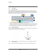
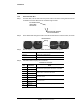


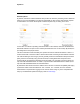
Table Of Contents

427-0100-00-12 Version 110 April 2019 13
WARNING - EAR Controlled Technical Data
Installation
Step 5 Route the PoE cable as shown below. The PoE cable is all that is required.
Ethernet
10-pin
connector
port
Pin 1
Back box
connector
Step 6 Secure the back box onto the wall mount bracket using the screwdriver to tighten the three
quarter-turn twist-lock assemblies.
1.3 Camera Connections
All connections for the camera are made to the back box assembly. The camera is simply plugged
into the back box.
1.3.1 Grounding
Ensure the camera is properly grounded. Failure to properly ground th
e camera can lead to
permanent damage to the camera. Typical to good grounding practices, the camera back box
chassis ground should be connected to the lowest resistance path possible.
1.3.2 Connecting Power
The camera is powered over Ethernet using IEEE 802.3af-2003 standard PoE switch or PoE
injec
tor. A conventional 24 Vac or 12 Vdc power supply can a
lso be used for powering the camera.
Prior to installing the camera onto the back box, ensure the power supply or circuit breaker is off.
1.3.3 Aim the Camera
Ensure the camera ball set screws are
loose so that the
camera ball can be pushed into its base slightly and rotated.
Camera ball
set screw (2)
Step 1 Set the camera ball into the back box aligning the
guide pins and screw the camera assembly onto
the back box.
Step 2 Aim the camera by manipu
late the camera ball
while viewing the image on the camera’s web
page. (See the diagram in Camera Placement.)
Then tighten the two set screws.
Step 3 Attach the sunshield for outdoor applications where
requir
ed.