
User's Guide
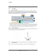
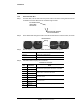

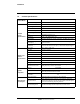


Table Of Contents

427-0100-00-12 Version 110 April 2019 12
WARNING - EAR Controlled Technical Data
Installation
1.2.9 Install the Back Box
Step 1 For each cable, use the Torx wrench to punch a hole in the
center of the grommet from the
underside. Insert the cable from the conduit though the hole.
Punch through grommet
from underside here
For surface mount
remove with
Torx wrench
Step 2 Push cables back through the seal so the seal is extended out of the back box, as shown:
Wrong
Correct
Inside back box
Step 3 Seal all exposed connections. Cable connections are not waterproof.
Connection Purpose
Ethernet Power and IP communications
10-pin connector Power I/O terminal: alarm I/O, audio I/O, Vac or Vdc power
Step 4 Terminate cables and plug into connectors.
Power & I/O Connector
Pin Connection Notes
1 Vac/Vdc power +
12 Vdc/24 Vac optional power when PoE is not available
2 Vac/Vdc power -
3 Alarm Output +
Relay contact: 1A max at 24 Vac/30 Vdc
4 Alarm Output -
5 Alarm Input +
Dry alarm contact
6 Alarm Input -
7 Audio In +
1 V P-P line level
8 Audio In -
9 Audio Out +
1 V P-P line level, connect to amplified speaker
10 Audio Out -