
User's Guide
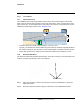
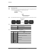


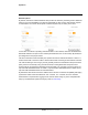
Table Of Contents

427-0100-00-12 Version 110 April 2019 11
WARNING - EAR Controlled Technical Data
Installation
Step 4 Click Onboard.
1.2.7 Camera Placement
For installations with incorpor
ating multiple cameras with on-board video analytics, the cameras’
fields of view of cameras should overlap to remove all dead zones in which a camera cannot see a
target “head to toe”, as demonstrated in the figure below. The camera’s on-board analytics must be
calibrated to detect targets. Refer to Video Analytics Setup.
4 m
• Install the camera at a height of approximately 4 m (13 ft) or more.
• Typically, you will direct the camera t
owards the ground with the maximum angle that still allows
the camera to image the area of interest. Include as little skyline as possible in the field of view.
• Ensure that cameras are on stable m
ounts with minimal vibrations and resistance to wind.
1.2.8 Install the Wall Mount
The wall mount bracket fits standard
electrical boxes. For surface mounting, secure the bracket, and
route the conduit through the side cover on the back box.
Twist-lock screws
Step 1 Using the screwdriver, undo the three quarter-turn twist-lock assemblies to release the
wall mount bracket.
Step 2 Secure the wall mount bracket using the screw holes for the in
stalled electrical box.