
User Manual

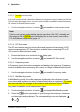


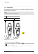


Table Of Contents

5 Operation
3. Use the
button to select the diode test function. The indicator will
be displayed.
4. Touch the tips of the probe across the diode or semiconductor junction under
test. Make a note of the value on the display.
5. Reverse the polarity of the probe, by interchanging the probe test locations.
6. Touch the tips of the probe across the diode or semiconductor junction under
test. Make a note of the new value on the display.
7. The diode or semiconductor junction can be evaluated as follows:
• If one of the readings displays a value (typically 0.400 V or 0.900 V) and
the other reading displays OL, the component is good.
• If both readings display OL, the component is open.
• If both readings are very small or 0, the component is shorted.
5.11 Streaming measurement data using Bluetooth
5.11.1 General
Some IR cameras from Flir Systems support Bluetooth communication, and to
those cameras you can stream measurement data from the meter. The data is
then merged into the result table in the IR image.
Streaming measurement data is a convenient way to add important information
to an IR image. For example, when identifying an overheated cable connection,
you may want to know the current in that cable.
5.11.2 Procedure
1. Pair the IR camera with the instrument. Refer to the camera manual for infor-
mation on how to pair Bluetooth devices.
2. Turn on the camera.
3. Turn on the meter.
4. Press the
on the meter to enable Bluetooth.
5. Choose the variable that you want to use (voltage, current, resistance, etc.).
Results from the meter will now automatically be displayed in the result table
in the top left corner of the IR camera screen.
#T559825; r.8008/8011; en-US 24