
User Manual

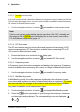


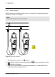


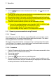
Table Of Contents

5 Operation
1. Set the function switch to the position.
2. Insert the black probe lead into the negative COM terminal and the red probe
lead into the positive
terminal.
3. Touch the tips of the probe across the part under test.
4. Read the capacitance value on the display.
Note
For very large capacitance values, it may take several minutes for the
measurement to settle and the final reading to stabilize.
5.9 Continuity test
WARNING
Do not do diode, resistance or continuity tests before you have removed the
power from the capacitors and from a device during a test. Injury to persons
can occur.
1. Set the function switch to the
position.
2. Insert the black probe lead into the negative COM terminal and the red probe
lead into the positive Ω terminal.
3. Use the
button to select continuity measurement. The indicator will
be displayed.
4. Touch the tips of the probe across the circuit or component under test.
5. If the resistance is less than 30 Ω, the meter will beep.
5.10 Diode test
WARNING
Do not do diode, resistance or continuity tests before you have removed the
power from the capacitors and from a device during a test. Injury to persons
can occur.
1. Set the function switch to the
position.
2. Insert the black probe lead into the negative COM terminal and the red probe
lead into the positive Ω terminal.
#T559825; r.8008/8011; en-US 23