
User's Manual
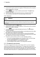
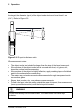
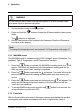
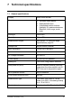
Table Of Contents
- 1 Disclaimers
- 2 Safety information
- 3 Introduction
- 4 Description
- 5 Operation
- 5.1 Powering the meter
- 5.2 Auto/Manual range
- 5.3 Current measurements
- 5.4 Voltage measurements
- 5.5 Resistance measurements
- 5.6 Capacitance measurements
- 5.7 Frequency measurements
- 5.8 Type K temperature measurements
- 5.9 Continuity
- 5.10 Diode test
- 5.11 IR temperature measurements
- 5.12 MAX/MIN mode
- 5.13 Peak hold
- 5.14 Temperature units
- 5.15 Streaming measurement data using Bluetooth
- 6 Maintenance
- 7 Technical specifications
- 8 Technical support
- 9 Warranties

5 Operation
2. Insert the black probe lead into the negative COM terminal and the red probe
lead into the positive Ω terminal.
3. Use the
button to select continuity measurement. The indicator
should be displayed.
4. Touch the tips of the probe across the circuit or component under test.
5. If the resistance is less than 30 Ω, the meter beeps continuously.
5.10 Diode test
WARNING
Do not do diode, resistance or continuity tests before you have removed the
power from the capacitors and from a device during a test. Injury to persons
can occur.
1. Set the function switch to the
position.
2. Insert the black probe lead into the negative COM terminal and the red probe
lead into the positive Ω terminal.
3. Use the
button to select the diode test function. The indicator
should be displayed.
4. Touch the tips of the probe across the diode or semiconductor junction under
test. Make a note of the value on the display.
5. Reverse the red and black test lead positions to reverse the test polarity.
6. Touch the tips of the probe across the diode or semiconductor junction under
test. Make a note of the new value on the display.
7. The diode or semiconductor junction can be evaluated as follows:
• If one of the readings displays a value (typically 0.400 V or 0.900 V) and
the other reading displays OL, the component is good.
• If both readings display OL, the component is open.
• If both readings are very small or 0, the component is shorted.
5.11 IR temperature measurements
The meter is equipped with a laser pointer diode, which is used as a targeting
pointer for the IR temperature measurements. The target of the measurement
should be larger than the size of the laser beam spot. As the distance from an ob-
ject increases, the spot size of the area measured by the meter becomes larger.
The meter’s field of view ratio is 8:1, meaning that if the meter is 8 cm (3.2″) from
#T559826; r.9072/9080; en-US 18