
Manual


LDU 78.1 Technical Manual, Rev. 12 May 2011
Page 26 of 36
8.9. Setpoint Output Commands – Sn, Hn, An
The LDU 78.1 has 2 logic outputs where the status depends on the weight value (setpoint). Each logic output
can be assigned an independent setpoint value (Sn) with a corresponding hysteresis/switch action (Hn) and
allocation (An – switch on the gross or the net weight).
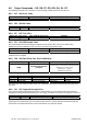
8.9.1. S n Setpoint Value
Master (PC / SPS) sends Slave (LDU XX.X) responds Meaning
S0 O+01500
Request: Setpoint S0 = 1500 d
S0 03000 OK
Setup: Setpoint S0 = 3000 d
S1 O+01500
Request: Setpoint S1 = 1500 d
S1 03000 OK
Setup: Setpoint S1 = 3000 d
8.9.2. H n Setpoint Hysteresis and Switching Action
The wished switching logic will be defined by the numeric value and the polarity of the setpoint hysteresis.
The outputs can operate as “normally closed” (negative polarity) or “normally open” (positive polarity).
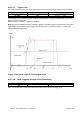
Example
Setpoint Hysteresis Weight Output open Output closed
S0 = 2000 kg H0 = -100kg increasing > 2100 kg
2100 kg
S0 = 2000 kg H0 = -100kg decreasing
2000 kg
< 2000 kg
S0 = 2000 kg H0 = 100kg increasing
2000 kg
> 2000 kg
S0 = 2000 kg H0 = 100kg decreasing < 1900 kg
1900 kg
Example for negative hysteresis and setpoint S0 = 2000 kg (line 1 + 2 of the table above):
When the weight is increasing between 0 kg and 2100 kg the logic output is “closed”. Once the weight exceeds
2100 kg then the logic output will be “open”. The logic output will get “closed” again when the weight value
drops below 2000 kg.
Example for positive hysteresis and setpoint S0 = 2000 kg (line 3 + 4 of the table above):
When the weight is increasing between 0 kg and 2000 kg the logic output is “open”. Once the weight exceeds
2000 kg then the logic output will be “closed”. The logic output will re-open again when the weight value drops
below 1900 kg.
Master (PC / SPS) sends Slave (LDU XX.X) responds Meaning
H0 O-00100
Request: neg. hysteresis setpoint S0
H0 100 OK
Setup: pos. hysteresis setpoint S0
H1 O-00100
Request: neg. hysteresis setpoint S1
H1 100 OK
Setup: pos. hysteresis setpoint S1
Allowed hysteresis values are within the range from –99999 to +99999 at a step size of 1.
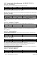
8.9.3. A n Allocation of Gros or Net Value
Allowed allocation Meaning
A0 = 0 Gros value controls setpoint S0
A0 = 1 Net value controls setpoint S0
A1 = 0 Gros value controls setpoint S1
A1 = 1 Net value controls setpoint S1
Master (PC / SPS) sends Slave (LDU XX.X) responds Meaning
A0 O+00000
Request: Gros for setpoint S0
A0 1 OK
Setup: Net for setpoint S0
A1 O-00000
Request: Gros for setpoint S1
A1 1 OK
Setup: Net for setpoint S1
Note: All changes to the setpoint settings have to be stored in the EEPROM using the SS command. See
chapter 8.11