
Manual


LDU 78.1 Technical Manual, Rev. 12 May 2011
Page 15 of 36
8.2. Calibration Commands – CE, CM n, CI, MR, DS, DP, CZ, CG, ZT, FD,
IZ, ZR, ZI, WT, TM, CS
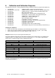
8.2.1. CE Read TAC* Counter / Open Calibration Sequence
With this command you can read the TAC counter (*TAC = Traceable Access Code) or you can open a
calibration sequence.
Master (PC / SPS) sends Slave (LDU XX.X) responds Meaning
CE E+00017 (example)
Request: TAC counter CE17
CE 17 OK
Calibration sequence active
This command must be issued PRIOR to any attempt to set the calibration parameters CM n, CI, MR, DS, DP,
CZ, CG, ZT, ZR, FD, LC, LN n or CS. In legal for trade applications the TAC counter can be used to check if
critical parameters have been change without re-verification. After each calibration the TAC counter increases
by 1.
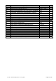
8.2.2. CM n Set Maximum Output Value
This command (CM n with n = 1, 2 or 3) is used to set up the maximum output value (respective the switching
point in multi range applications). Permitted values are from 1 to 99 999.
Master (PC / SPS) sends Slave (LDU XX.X) responds Meaning
CM 1 M+030000
Request: CM 1 = 30 000 d
CE E+00017 (example)
Request: TAC counter CE17
CE 17 OK
Calibration sequence active
CM 1 50000 OK
Setup: CM 1 = 50 000 d
This value will determine the point at which the output will change to “oooooo”, signifying over-range respective
the point at which the output will change the measuring range / interval size.
Application CM 1 = MAX 1 CM 2 = MAX 2 CM 3 = MAX 3
Single range CM 1 = 1...99 999
CM 2 = 0
(means CM 2 not used)
CM 3 = 0
(means CM 3 not used)
Dual range or dual interval
( Command MR)
CM 1 = 1...MAX 1 CM 2 = MAX 1...99 999
Triple range or triple interval
Teilungen ( Befehl MR)
CM 1 = 1...MAX 1 CM 2 = MAX 1...MAX 2 CM 3 = MAX 2...99 999
It is necessary: 1 MAX 1 < MAX 2 < MAX 3 99 999
Note: The range, in which a scale can be set to zero (SZ) or automatic zero tracking (ZT) is active, is +/- 2% of
CM value. Factory default: CM1 = 99 999, CM 2 = 0, CM 3 = 0
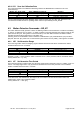
8.2.3. CI Set Minimum Output Value
This command is used to set up the minimum output value. Permitted values are from – 99 999 to 0.
Master (PC / SPS) sends Slave (LDU XX.X) responds Meaning
CI I–000009
Request: CI = –9 d
CE E+00017 (example)
Request: TAC counter CE17
CE 17 OK
Calibration sequence active
CI –10000 OK
Setup: CI = –10 000 d
This value will determine the point at which the output will change to “uuuuuu”, signifying under-range.
Note: In bipolar applications (e.g. force- or torque measurements) this parameter defines the max. output value
for input signals with negative sign. Factory default: CI = –9
8.2.4. MR Set Multi-range / Multi-interval
This command is only relevant, if CM 2 > 0 or CM 3 > 0. Is this the case,then this command defines, if the
application is multi-range or multi-interval. Permitted values are 0 (Multi-interval) or 1 (Multi-range).
Master (PC / SPS) sends Slave (LDU XX.X) responds Meaning
MR M+00000
Request: MR = 0 (Multi-interval)
CE E+00017 (example)
Request: TAC counter CE17
CE 17 OK
Calibration sequence active
MR 1 OK
Setup: MR = 1 (Multi-range)
Note: Single range applications ignore this parameter.