
Manual


LDU 78.1 Technical Manual, Rev. 12 May 2011
Page 10 of 36
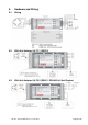
5.4. Terminal Configuration
LDU 78.1
UA 73.2 UA 77.1 Function
Pin no.
0 Gnd (Shield) Gnd (Shield) Common Ground
1 +Exc + Exc + Excitation for load cell
2 + Sens + Sens + Sense for load cell
3 + Sig + Sig + Signal
4 – Sig – Sig – Signal
5 – Sen – Sen – Sense for load cell
6 – Exc – Exc – Excitation for load cell
7 Gnd Gnd Signal ground / 0 V DC
8 NC NC Not connected
9 NC NC Not connected
10 + Rx RxD (RS232) Receive
11 - Rx Gnd (RS232) UA 73.2: Receive / UA 77.1: Common ground RS232
12 - Tx Gnd (RS232) UA 77.1: Senden / UA 77.1: Common ground RS232
13 + Tx TxD (RS232) Transmit
14 0 In 0 In Digital input 0 (with reference to ground)
15 0 out 0 out Digital output 0 (with reference to ground)
16 1 In 1 In Digital input 1 (with reference to ground)
17 1 Out 1 Out Digital output 1 (with reference to ground)
18 + PWR + PWR Power supply 12...24 V DC
19 Gnd Gnd Common ground / 0 V DC
Remarks:
UA 73.2 (see chapter 5.3) is prepared for full-duplex operation
Valid for half-duplex operation: pin no. 10 + 13 = A and pin no. 11 + 12 = B
UA 77.1 with integrated RS422/RS232 converter (see chapter 5.2)
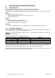
5.5. Load Cell Connection
The load cell wiring should be made carefully before energizing to avoid damages to the amplifier and the load
cells. The input resistance of the load cells that you want to connect should be more than 250 Ω.
The sense pins of the instrument should be connected. In 4-wire installations the switches SW1 and SW2 (see
chapter 5.1) have to be short circuited.
Flintec load cell; 4 wire connection Flintec load cell; 6 wire connection