Load Cell Digitizing Unit Type LDU 78.1 TECHNICAL MANUAL Firmware Version 78.183.v.2.50 or higher Hardware Version 78.101.5.v.3.00 Document No. G119 Rev12 GB Flintec GmbH Bemannsbruch 9 74909 Meckesheim GERMANY www.flintec.
Table of Contents: 1. Safety Instructions .................................................................................................................................... 4 2. Declaration of Conformity ........................................................................................................................ 5 3. Introduction and Specifications ............................................................................................................... 6 4.
8.5. Taring and Zeroing Commands – SZ, ZA, RZ, ST, RT ..........................................................................21 8.5.1. 8.5.2. 8.5.3. 8.5.4. 8.5.5. 8.6. SZ Set System Zero ....................................................................................................................................... 21 ZA Set Averaged System Zero ....................................................................................................................... 21 RZ Reset Zero ..............
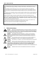
RIGHTS AND LIABILITIES All rights reserved. No part of this publication may be reproduced, stored in a retrieval system, or transmitted in any form or by any means, mechanical, photocopying, recording, or otherwise, without the prior written permission of Flintec GmbH No patent liability is assumed with respect to the use of the information contained herein. While every precaution has been taken in the preparation of this book, FLINTEC assumes no responsibility for errors or omissions.
2. Declaration of Conformity 0 EG-Konformitätserklärung EC-Declaration of Conformity Monat/Jahr: month/year: 11/2010 Hersteller: Manufacturer: Flintec GmbH Anschrift: Address: Bemannsbruch 9 D-74909 Meckesheim Deutschland / Germany Produktbezeichnung: Product name: LDU 78.
3. Introduction and Specifications The model LDU 78.1 is a very precise high-speed digital amplifier for weighing and force measurements with strain gauge (SG) sensors. The LDU 78.1 can be used in legal for trade as well as for industrial applications. The device features full multi-drop communications capability and can be programmed via a straightforward ASCII command set. The LDU XX.X series and the amplifier DAS 72.1 with on-board digital display, use the same command set.
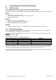
4. Communications and Getting started 4.1. Serial Interface Communicating with the LDU 78.1 digitizer is carried out via the RS422/RS485 port. The data format is the familiar 8/N/1 structure (8 data bits, no parity, 1 stop bit). Available baud rates via the RS422/RS485 port are as follows: 9 600, 19 200, 38 400, 57 600 or 115 200 baud. RS422: Connection using a 4 wire technique Point-to-Point connection, i.e.
4.3. Baud Rate / Device Address Baud Rate: For baud rate setup use command BR, see chapter 8.10 Factory default: 9 600 baud Device Address: For address setup use command AD, see chapter 8.10 Factory default: Address 0 Setting the device address to 0 will set the continuously active mode, where the device becomes permanently active, and will listen and respond to any command on the bus, without the need for an OP xxx command. Note: The LDU XX.
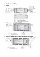
5. Hardware and Wiring 5.1. Wiring 5.2. With Unit Adapter UA 77.1 (RS232) 5.3. With Unit Adapter UA 73.2 (RS422 / RS485 Full-/Half-Duplex) LDU 78.1 Technical Manual, Rev.
5.4. Terminal Configuration LDU 78.1 Pin no. 0 1 2 3 4 5 6 7 8 9 10 11 12 13 14 15 16 17 18 19 UA 73.2 Gnd (Shield) +Exc + Sens + Sig – Sig – Sen – Exc Gnd NC NC + Rx - Rx - Tx + Tx 0 In 0 out 1 In 1 Out + PWR Gnd UA 77.
6. Calibration and Calibration Sequence The calibration of LDU 78.1 is only possible after starting a calibration sequence (compare with chapter 8.2). Command CE: Command CM1 / CM2 /CM3: Command CI: Command MR: Command DS: Command DP: Command CZ: Command CG: Command ZT: Command IZ: Command ZR: Command ZI: Command WT: Command FD : Command CS : Calibration enable – returns the current TAC value Calibrate maximum display – sets the max.
7. Commands – Overview Command Short description AD Communication: Device Address An Setpoints: Output of Gros (0) or Net (1) for setpoints S0 and S1 Parameter value 0...
Command SL SN S0/S1 SR SS ST SW SX SZ Short description Auto-transmit: Send Data String „Average/Gross/Status“ continuously Auto-transmit: Send Net Value continuously Setpoints: Setup of Setpoints S0 and S1 Reset Firmware (Warm Start) Save the Setpoint Data (S0, S1, H0, H1, A0 and A1) to the EEPROM Scale function: Set Tare and Switch to Net Indication Auto-transmit: Send Data String „Net/Gross/Status“ continuously Auto-transmit: Send ADC Sample Value continuously Scale function: System Zero Point Paramete
8. Commands Description For better clarity, all commands are divided into groups as described on the following pages. 8.1. System Diagnosis Commands – ID, IV, IS, SR, RS Use these commands you get the LDU XX.X type, firmware version or device status. These commands are sent without parameters. 8.1.1. ID Get Device Identity Master (PC / SPS) sends ID Slave (LDU XX.X) responds D:7813 The response to this request gives the actual identity of the active device.
8.2. Calibration Commands – CE, CM n, CI, MR, DS, DP, CZ, CG, ZT, FD, IZ, ZR, ZI, WT, TM, CS 8.2.1. CE Read TAC* Counter / Open Calibration Sequence With this command you can read the TAC counter (*TAC = Traceable Access Code) or you can open a calibration sequence. Master (PC / SPS) sends Slave (LDU XX.
8.2.5. DS Set Display Step Size This command allows the output to step up or down by a unit other than 1. Permitted values are 1, 2, 5, 10, 20, 50, 100 and 200. Master (PC / SPS) sends DS CE CE 17 DS 50 Slave (LDU XX.X) responds S+00002 E+00017 (example) OK OK Meaning Request: Step size 2 Request: TAC counter CE17 Calibration sequence active Setup: Step size 50 Legal for trade applications allow for up to 10 000 intervals. The allowed step size has to be considered. 8.2.6.
8.2.10. FD Reset to Factory Default Settings This command puts the LDU back to a known state. The data will be written to the EEPROM and the TAC will be incremented by 1. Note: All calibration and setup information will be lost by issuing this command! Master (PC / SPS) sends CE CE 17 FD 8.2.11. IZ Slave (LDU XX.
8.2.16. CS Save the Calibration Data This command results in the calibration data being saved to the EEPROM and causes the TAC to be incremented by 1. Master (PC / SPS) sends CE CE 17 CS Slave (LDU XX.X) responds E+00017 (example) OK OK Meaning Request: TAC counter CE17 Calibration sequence active Calibration values saved The CS command saves all of the calibration group values, as set by CZ, CG, CM n, DS, DP and ZT.
8.4. Filter Setting Commands – FM, FL, UR A digital filter can be set which will eliminate most of the unwanted disturbances. The commands FM and FL are used to define the digital filter settings, the command UR is used to define an averaging of up to 128 measurement values. Please note that these filters are positioned immediately after the A/D Converter and therefore affect all aspects of the weighing operation. 8.4.1. FM Filter Mode This command defines the filter mode.
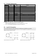
8.4.3. UR Update Rate and Averaging Depending on the selected filter mode this command defines an averaging for the output value. The permitted settings are from 0 to 7 (see table below). The average value will always be calculated from 2UR measurement values. LDU 78.1 allows for following settings: UR Measurement values / second 0 1 1 2 2 4 3 8 4 16 5 32 6 64 7 128 Check / Setup of the averaging: Master (PC / SPS) sends UR UR 4 WP Slave (LDU XX.
8.5. Taring and Zeroing Commands – SZ, ZA, RZ, ST, RT The following commands allow you to set and reset the zero and tare values. The zero set up during calibration remains the ‘true zero’ but the new ‘current zero’ can be set up by using the SZ command. If the SZ command is issued and accepted then all weight values will then be based on the new ‘current zero’. Please remember that the zero value will be subject to the Zero tracking function if enabled.
8.6. Output Commands – GG, GN, GT, GS, GW, GA, GL, OF The following commands “Get” the gross, net, tare and ADC sample values from the LDU 78.1. 8.6.1. GG Get Gross Value Master (PC / SPS) sends GG 8.6.2. GN Slave (LDU XX.X) responds N+01.000 Meaning Net value: 1.000 d Get Tare Value Master (PC / SPS) sends GT 8.6.4. GS Meaning Gross value: 1.100 d Get Net Value Master (PC / SPS) sends GN 8.6.3. GT Slave (LDU XX.X) responds G+01.100 Slave (LDU XX.X) responds T+00.
8.6.7. GL Get Data String “Average, Gross and Status“ Master (PC / SPS) sends Slave (LDU XX.X) responds GL L+000100+0011005109 (example) Meaning Average value: +000100 d (no decimal point) Gross value: +001100 d (no decimal point) Status bit 1: 5 (not used) Status bit 2: 1 (Hex) Check sum: 09 (Hex) For check sum, status bit 1 and status bit 2 see command GW. 8.6.8.
8.7. Auto–transmit Commands – SG, SN, SX, SW, SA, SL The following commands allow the gross weight or net weight values to be continuously sent. Continuous transmission start as soon as the relevant command has been issued and finishes when any other valid command is accepted by the LDU 78.1. The data output rate will depend on the baud rate being used e.g. with a baud rate of 9 600, approximately 100 values per second can be transmitted. Note: All auto-transmit commands will only work if the LDU 78.
8.8. Commands for External I/O Control – IN, IO, IM The LDU 78.1 has 2 independent logic inputs and 2 independent logic outputs. These inputs and outputs can be configured and controlled completely via the LDU. The logic inputs can be read directly by the host application and the logic outputs can be fully controlled via the setpoint commands.
8.9. Setpoint Output Commands – Sn, Hn, An The LDU 78.1 has 2 logic outputs where the status depends on the weight value (setpoint). Each logic output can be assigned an independent setpoint value (Sn) with a corresponding hysteresis/switch action (Hn) and allocation (An – switch on the gross or the net weight). 8.9.1. S n Setpoint Value Master (PC / SPS) sends S0 S0 03000 S1 S1 03000 Slave (LDU XX.
8.10. Communication Setup Commands – AD, BR, DX, TD, OP, CL 8.10.1. AD Device Address This command can set up the device address in the value range from 0 to 255. Master (PC / SPS) sends AD AD 49 Slave (LDU XX.X) responds A:000 OK Meaning Request: Address 0 (= factory default) Setup: Address 49 Setting the device address to “0“ will cause the device to be permanently active, listening and responding to every command on the bus without the need for an OP command.
8.11. Save Calibration and Setup Data Commands – CS, WP, SS, GI, PI The calibration and setup parameters can be divided in 3 groups: Calibration: CM, DS, DP, CZ, CG, ZT, IZ and FD, saved by command CS Setup: FL, FM, NR, NT, BR, AD, DX and other, saved by command WP Setpoints: S0, S1, H0, H1, A0, A1, saved by command SS Note: Calibration data can only be saved if the TAC code is known and precedes the CS command. See the CE and CS commands in chapter 8.2.
8.12. Trigger Commands – SD, MT, GA, TE, TR, TL, SA Note: All changes to the trigger commands have to be stored in the EEPROM using the WP command. See chapter 8.11 8.12.1. SD Start Delay Time This command defines a time delay between the trigger and the start of the measurement. Setting range: 0 ms to 500 ms. Master (PC / SPS) sends SD SD 200 Slave (LDU XX.
8.12.6. TL Trigger Level This command defines a level for a rising edge trigger on the measurement signal. Setting range: 0 to 99999. Master (PC / SPS) sends TL TL 1000 Slave (LDU XX.X) responds T+99999 OK Meaning Request: TL = 99999 Setup: TL = 1000 In the example a new measurement cycle would automatically start, if the signal exceeds 1000 d (e.g. 100,0 g; trigger commands SD and TL).
8.13. Re-Trigger Commands – RW, TT, TS, DT, TW, TI, HT Note: All changes to the re-trigger commands have to be stored in the EEPROM using the WP command. See chapter 8.11 8.13.1. RW Trigger Window for Re-Trigger Function This command defines a trigger window in unit d (digits) around the current cycle average value. If the signal leaves this window even for one sample, then the averaging over the time period TT will be started again.
8.13.6. TI Averaging Time for Automatic Taring This command defines the averaging time for the automatic taring. Within this time period the system calculates an averaged tare value. Default setting: TI = 0 ms. Master (PC / SPS) sends TI TI 200 8.13.7. HT Slave (LDU XX.X) responds T+00000 OK Meaning Request: TI = 0 ms Setup: TI = 200 ms Hold time for Violation of Setpoint Limit This command defines the hold time for any violation of the setpoint limit.
9. Use in “Approved” Applications The term “approved” applies whenever the weighing application is intended to be used for “legal-for-trade” weighing – that is, money will change hands according to the weight result. Such applications are bound by the legal metrology regulations of the relevant governments around the World, but most countries will comply with either the relevant EN’s (Euro Norms) or the relevant OIML (Organisation Internationale de Metrologie Legale) recommendations. The LDU 78.
10. Updates – Firmware Download For a software update the LDU xx.x amplifier has to be connected with a Windows PC via the serial interface (4-wire connection; RS485/RS422 respective RS485/RS232 converter). The solder pads SW4 on the bottom side of the PCB must be closed before switching on. After the download the solder pads must be opened again. A download is accomplished with help of our program “PROG78”. Firmware update for LDU xx.x series: First all necessary files (LduDownload.exe, progXX.
LDU 78.1 Technical Manual, Rev.
www.flintec.com LDU 78.1 Technical Manual, Rev.