
Manual


LDU 68.1 & 68.2 Technical Manual, Rev. 12 January 2010
Page 12 of 28
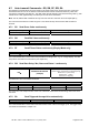
7. Commands – Overview
Command Short description Parameter value Page
AD
Communication: Device Address 0...255 23
A0/A1
Setpoints: Output of Gros Value (0) or Net Value(1) 0 or 1 22
BR
Communication: Baud Rate 9600…115200 baud 23
CE
Calibration: Open Calibration Sequence; Read TAC Counter 0...65535 14
CI
Calibration: Minimum Output Value –99999...0 d 14
CG
Calibration: Set Calibration Gain (Span) at Load > Zero 0...99999 15
CL
Communication: Close Device None 23
CM
Calibration: Set Maximum Output Value 1...99999 d 14
CS
Save the Calibration Data (CM, CI, DS, DP, CZ, CG, etc.) to EEPROM None
15, 24
CZ
Calibration: Set Calibration Zero Point – scale without load None
14
DP
Calibration: Set Decimal Point Position 0...5 14
DS
Calibration: Set Display Step Size 1, 2, 5, 10…, 200 14
DX
Communication: Set Half-duplex (0) or Full-duplex (1) 0 or 1 23
FD
Factory default settings: Write data to EEPROM (TAC protected) None 15
FF
Digital filter: Moving Average 0…15 17
FL
Digital filter: Filter Cut-off Frequency 0...7 17
GA
Trigger function: Get Average Value None 25
GF
Output: Get Filtered Value None
19
GG
Output: Get Gross Value None
19
GI
Saves an image file from the LDU’s EEPROM None 24
GN
Output: Get Net Value None
19
GS
Output: Get ADC Sample Value None
19
GT
Output: Get Tare Value None
19
GW
Output: Get Data String “Net/Gross/Status“ None
19
H0/H1
Setpoints: Hysteresis for Setpoint S0 (H0) or S1 (H1) -99999...+99999 d 22
ID
Device information: Identify Device None
13
IM
Digital output: Enable Output for External Control 0000...0011 21
IN
Digital input: Input Status None 21
IO
Digital output: Output Status 0000...0011 21
IS
Device information: Identify Device Status None
13
IV
Device information: Identify Firmware Version None
13
MT
Trigger function: Measuring Time for Averaging 0...500 ms 25
NR
Motion detection: No-motion Range 0...65535 d 16
NT
Motion detection: No-motion Time Period 0...65535 ms 16
OP
Communication: Open Device xxx 0...255 23
PI
Download a saved image file to the LDU’s EEPROM None 24
RS
Device information: Read serial number None 13
RT
Scale function: Reset Tare and Switch to Gross Indication None
18
RZ
Scale function: Reset Zero Point None
18
SA
Auto-transmit: Send Triggered Average Value automatically None 20, 25
SD
Trigger function: Start Delay 0...500 ms 25
SF
Auto-transmit: Send Filtered Net Value continuously (Display Mode only) None
20
SG
Auto-transmit: Send Gross Value continuously None
20
SN
Auto-transmit: Send Net Value continuously None
20
S0/S1
Setpoints: Setup of Setpoints S0 and S1 -99999...+99999 d 22
SR
Reset Firmware (Warm Start) None
13
SS
Save Setpoint Data (S0, S1, H0, H1, A0 and A1) to EEPROM None 24
ST
Scale function: Set Tare and Switch to Net Indication None
18
SW
Auto-transmit: Send Data String „Net/Gross/Status“ continuously None
20
SZ
Scale function: Set Zero None 18
TD
Communication: Transmission delay 0…255 ms 23
TE
Trigger function: Trigger on Rising Edge (1) or Falling Edge (0) 0 or 1 25
TL
Trigger function: Trigger Level 0...99999 d 26
TR
Trigger function: Software Trigger None 25
UR
Digital filter: Update Rate 0...2 17
WP
Save the Setup Data (FL, NR, NT, AD, BR, DX) to EEPROM None 24
ZI
Calibration: Initial Zero Range 0...99999 d 15
ZT
Zero Tracking: Disable (0) or Enable (1) 0 or 1 15