
Manual


LDU 68
.
5.4. T
LDU 6
8
Pin n
o
0
1
2
3
4
5
6
7
8
9
10
11
12
13
14
15
16
17
18
19
Remarks:
UA 7
3
Valid
UA 7
7
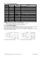
5.5. L
The load c
e
cells. The i
The sense
chapter 5.
1
Flintec lo
a
.1 & 68.2
T
ec
h
erminal
8
.x
U
A
o
.
Gnd (S
h
+Exc
+ Sens
+ Sig
– Sig
– Sen
– Exc
Gnd
NC
NC
+ Rx
- Rx
- Tx
+ Tx
0 In
0 out
1 In
1 Out
+ PWR
Gnd
3
.2 (see cha
p
for half-dupl
7
.1 with inte
g
oad Cell
e
ll wiring sh
o
nput resista
n
pins of the i
n
1
) have to b
e
a
d cell; 4 wir
e
h
nical Manual
Configu
A
73.2
h
ield)
p
ter 5.3) is
p
ex operatio
n
g
rated RS42
Conne
c
o
uld be mad
e
n
ce of the lo
a
n
strument s
h
e
short circui
t
e
connection
,
Rev. 12 Ja
n
r
ation
UA 77
.
Gnd (Shield)
+ Exc
+ Sens
+ Sig
– Sig
– Sen
– Exc
Gnd
NC
NC
RxD (RS232
Gnd (RS232
Gnd (RS232
TxD (RS232
)
0 In
0 out
1 In
1 Out
+ PWR
Gnd
p
repared for
f
n
: pin no. 10
+
2/RS232 co
n
c
tion
e
carefully b
e
a
d cells that
h
ould be co
n
t
ed.
n
uary 2010
.
1
)
Co
m
+ E
x
+ S
e
+ Si
– Si
– S
e
– E
x
Sig
n
Not
Not
2
) Re
c
) UA
7
) UA
7
) Tra
n
Digi
Digi
Digi
Digi
Po
w
Co
m
f
ull-duplex o
+ 13 = A an
n
verter (see
e
fore energi
z
you want to
n
nected. In 4
-
Fli
n
m
mon Groun
d
x
citation for l
o
e
nse for load
gnal
gnal
e
nse for load
x
citation for l
o
n
al ground /
0
connected
connected
c
eive
7
3.2: Receiv
e
7
7.1: Sende
n
n
smit
tal input 0 (w
tal output 0 (
w
tal input 1 (w
tal output 1 (
w
w
er supply 12
m
mon ground
p
eration
d pin no. 11
chapter 5.2
)
z
ing to avoi
d
connect sh
o
-
wire install
a
n
tec load cel
Functi
o
d
o
ad cell
cell
cell
o
ad cell
0
V DC
e
/ UA 77.1:
C
n
/ UA 77.1:
C
ith reference
w
ith referenc
e
ith reference
w
ith referenc
e
...24 V DC
/ 0 V DC
+ 12 = B
damages t
o
o
uld be more
a
tions the sw
l; 6 wire con
n
on
C
ommon gro
u
C
ommon gro
u
to ground)
e to ground)
to ground)
e to ground)
o
the amplifi
e
e
than 250 Ω
.
w
itches SW1
nection
Page 10 o
f
u
nd RS232
u
nd RS232
e
r and the lo
a
.
and SW2 (s
e
f
28
a
d
e
e