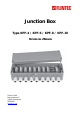
Junction Box Type KPF-4 / KPF-6 / KPF-8 / KPF-10 TECHNICAL MANUAL Flintec GmbH Bemannsbruch 9 74909 Meckesheim GERMANY www.flintec.
RIGHTS AND LIABILITIES All rights reserved. No part of this publication may be reproduced, stored in a retrieval system, or transmitted in any form or by any means, mechanical, photocopying, recording, or otherwise, without the prior written permission of Flintec GmbH No patent liability is assumed with respect to the use of the information contained herein. While every precaution has been taken in the preparation of this book, FLINTEC assumes no responsibility for errors or omissions.
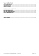
TABLE OF CONTENTS RIGHTS AND LIABILITIES................................................................................................................................ 2 SAFETY INSTRUCTIONS ................................................................................................................................. 2 TABLE OF CONTENTS ..................................................................................................................................... 3 INTRODUCTION AND TECHNICAL DATA ...
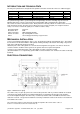
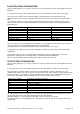
INTRODUCTION AND TECHNICAL DATA The Polyester junction box is designed for the parallel connection of load cells. There are 4 different types: Type KPF-4 KPF-6 KPF-8 KPF-10 No.
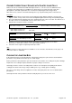
LOAD CELL CABLE CONNECTION Only the cable gland nut (see (1) in fig.1) must be loosened. The bottom part of the cable gland must remain tightened. It is absolute necessary to check all the bottom parts of the cable glands for a firm seat in the housing! Then you have to feed the load cell cable through the cable gland unless the shrink tube has fully disappeared in the box, because sealing and strain relief must be done at the cable and not at the shrink tube.
CORNER CORRECTION AT SCALES WITH FLINTEC LOAD CELLS Flintec load cells are manufactured with rather tight tolerances, so in most cases an additional corner correction is not required. The best conditions are achieved if you use load cells of the same class (Designation is done with capital letters A to I on the load cell package besides the type label). Hint: Corner errors can have a mechanical background, e.g. sloped mounting surface of the load cell. Procedure: 1. Get the display value for each corner.
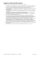
SUMMARY OF IMPORTANT SERVICE HINTS At each re-calibration or repair following checks or actions have to be done: 1. All bottom parts of the cable glands are sealed to the housing with some gasket. You have to check the existence and the condition of these gaskets, the gaskets have to be replaced if required. 2. You have to check all bottom parts of the cable glands for a firm seat in the housing.
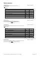
SERVICE MATERIAL Service kit no.1 for load cells with maximum capacity above 30 t with ring spanner Parts list: Description KP cable gland M16 x 1,5, clamping range 6.5 – 9 mm Silicone cover sealing (red) Silicon grease, 6 g Dry tablet Gasket 22 x 16 x 1.5 mm Gasket 18 x 12 x 1.5 mm Round cord, 6 mm black Plastic blind plug M16 x 1.5 Plastic blind plug M12 x 1.5 Ring spanner for M16 cable glands Article no.: 5200-U1 Article no.