ECONOMY 1/2 HP SHALLOW WELL JET PUMP FW1005 0706B Supersedes 0706 IL0607 IMPORTANT INSTALLATION PRECAUTIONS Please read and save these instructions. Read carefully before attempting to assemble, install, operate or maintain the product described. Protect yourself and others by observing all safety information. Failure to comply with instructions could result in personal injury and/or property damage! Retain instructions for future reference. 95 North Oak St. • Kendallville, IN 46755 © Copyright 2006.
General Safety Information Carefully read and follow all safety instructions in this manual and on pump. Keep safety labels in good condition. Replace missing or damaged safety labels. Never examine, make wiring changes or touch the motor before disconnecting the main electrical supply switch. Unpacking 1. Open carton and remove package that has been packed with the pump. This package contains the pressure switch. 2. Remove pump from carton. 3. Check for loose, missing or damaged parts.
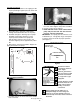
Assembly (Continued) 2. Screw in pressure switch to 1/4” tapping on side of pump hand tight. Tighten pressure switch with wrench. 2. Screw elbow fitting to discharge tee. Push flexible hose onto elbow. Tighten clamp with screwdriver. 3. Connect service line to tank Tee. 4. NOTE: DO NOT install a check valve between pump and pressure tank. This will cause the pressure switch to malfunction. IMPORTANT: Your pump pressure switch is set for a 20-40 PSI (1.4 - 2.
MOTOR Assembly (Continued) M To reduce the risk of electric shock, install with motor and all electrical components above the top grade level of sump. This pump is not submersible. Use wire size specified in wiring Chart C. If possible connect pump to a separate branch circuit with no other appliances on it. If motor wiring diagram differs from diagram shown below, follow diagram on motor. Wire motor for correct voltage.
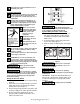
1. During the first few hours of operation, inspect the pump, piping and any auxiliary equipment used in connection with the unit. 2. Check for leaks, excessive vibration or unusual noise. IMPORTANT: Flow into well must at least equal flow out through pump! See Performance Chart B. Priming Port Main Power Box Fuse Box or Switch IL0126 Figure 5 1. Remove priming plug. 2. Fill pump and suction pipe with water until water runs out of the priming port. 3. Replace priming plug, hand tight.
Winterizing If pump is located in an area subject to freezing temperature, the pump should be drained when it is not in service or in danger from freezing. Winterizing (Continued) 1. Disconnect power. 2. Slowly and carefully release all water pressure. 3. Drain suction pipe to a point below the frost line. 4. Drain all piping exposed to freezing temperatures. 5. Remove the 1/4” drain plug located on the bottom of the pump body (See Figure 1). 6. Remove the priming plug from service tee to vent pump. 7.
Remove Mechanical Seal Cased/Dug Well Installation Priming Plug Suction Pipe Priming Tee Well Seal Standing Water Level (Pump Off) Drawdown Water Level 10 - 20’ (Pump On) At Least 5 Feet IL0173 Figure 8 Press in Seal IL0170 Figure 11 Driven Point Installation Check Valve IL0168 Steel Drive Pipe Figure 9 If necessary, press with cardboard and pipe Drive Coupling 3/4” pipe - press carefully Well Point Driven Point Cardboard washer protects seal face IL0171 Seal Figure 12 Lake Installation Se
TROUBLESHOOTING CHART SYMPTOM A. MOTOR WILL NOT RUN B. MOTOR RUNS HOT AND OVERLOAD KICKS OFF C. MOTOR RUNS BUT NO WATER IS DELIVERED (*) NOTE: Check prime before looking for other causes. Unscrew priming plug and see if there is water in priming hole D. PUMP DOES NOT DELIVER WATER TO FULL CAPACITY (ALSO CHECK POINT 3 IMMEDIATELY ABOVE) POSSIBLE CAUSE(S) CORRECTIVE ACTION 1. Disconnect switch is off. 1. Be sure switch is on 2. Fuse is blown. 2. Replace fuse 3. Starting switch is defective. 3.
TROUBLESHOOTING CHART (Continued) SYMPTOM E. PUMP PUMPS WATER, BUT DOES NOT SHUT OFF F. PUMP CYCLES TOO FREQUENTLY G. AIR SPURTS FROM FAUCETS LITTLE OR NO WATER POSSIBLE CAUSE(S) CORRECTIVE ACTION 1. Pressure switch is out of adjustment or contacts are “frozen” 1. Adjust or replace pressure switch 2. Faucets have been left open 2. Close faucets 3. Ejector or impeller is clogged 3. Clean ejector or impeller 4. Water level in well is lower than estimated 4.
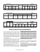
Specifications Chart A Motor HP 1/2 Volts Phase HZ RPM Motor Connected For 115/230V 1 60 3450 115V Suction Discharge Dimensions Pressure Switch Setting Inlet Outlet H W L Ship Wt. Lbs. 30/50 PSI 1-1/4” 1” 8” 10” 17” 36 Pump Performance HP Suction Lift (Feet) 1/2 5 15 25 Chart B Gallons Per Minute Capacity At Discharge Pressure PSI 20 30 40 50 10.1 7.3 4.5 9.6 7.0 4.2 7.8 4.5 3.8 5.5 3.2 2.7 Shut Off PSI 80 79 79 Wiring And Fuse Size Motor HP 1/2 Max.