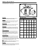
Installation Instructions and Parts Manual “CPJ” SERIES JET PUMPS ® Shallow Well Jet Pumps 1/3 - 1/2 HP “CPJS” SHALLOW WELL IL0189 3/4 - 1-1/2 HP “CPJS” SHALLOW WELL IL0190 Convertible Jet Pumps 1/2 HP “CPJ” CONVERTIBLE IL0192 3/4 - 1-1/2 HP “CPJ” CONVERTIBLE IL0188 Ejectors (Purchase separately) Top, if used for shallow well Top TOP IL0195 Shallow Well Ejector for lifts to 25 ft. IL0194 Convertible Ejector For Shallow or Deep well applications (4 inch inside diameter wells).
SAFETY INFORMATION 6. This product contains chemicals known to the State of California to cause cancer and birth defects or other reproductive harm. 7. Hazardous Pressure! Install pressure relief valve in discharge pipe. Release all pressure on system before working on any component. 8. Do not use to pump flammable or explosive fluids such as gasoline, fuel oil, kerosene, etc. Do not use in flammable and/or explosive atmospheres. DANGER: 1.
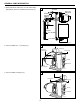
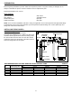
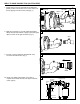
GENERAL PUMP INFORMATION Typical Pump Setup 1 Convertible jet pumps are designed for use in these applications: 1. Shallow wells (0 - 25 ft. lift) where ejector bolts to pump (Fig. 1) 3/4 or 1 in. Discharge Pipe Discharge to Home Suction Lift 1-1/4 in. Suction Pipe 25 ft. Max Pipe Support Water Level Foot Valve 2. Deep wells where well ID is 4” or more and a two pipe ejector is installed in the well. (Fig. 2) 2 Discharge to Home Suction Pipe See Table B Suction Lift IL1187 3/4 or 1 in.
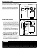
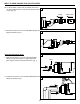
GENERAL PUMP INFORMATION 3. Deep wells where well ID is 2” or more and a single pipe (packer) ejector is installed in the well. (Fig. 3) 3 Discharge to Home 3/4 or 1 in. Discharge Pipe Suction Pipe See Table B Pipe Support 2 in. ID Well Foot Valve IL0209 4. CPJ Convertible 3/4 - 1-1/2 HP (Fig. 4) 4 Pressure Switch Discharge Diaphragm Control Valve Priming Port Suction Pressure Pressure Gauge Tapping IL0188 5 5. CPJ Convertible 1/2 HP (Fig.
GENERAL PUMP INFORMATION 6. CPJ Shallow Well 1/3 - 1/2 HP (Fig. 6) 6 Pressure Switch Priming Port Discharge Suction Shallow Well Ejector IL0189 Ventilation Ventilation and drainage must be provided to prevent damage to the motor from heat and moisture. Freezing The pump and all piping must be protected from freezing. If freezing weather is forecast, drain pump or remove completely from the system.
PREPARATION Before beginning installation of product, make sure all parts are present. If any part is missing or damaged, do not attempt to assemble the product. Contact customer service for replacement parts. Estimated Installation Time: 2 hours.
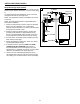
Installing PIPING IN WELL hen connecting a drive point (Fig. 2) a check valve must W be used in the suction line in place of a foot valve. For easy priming connect the check valve as close to the well as possible. All piping from the well to the pump should slope slightly upward with no sagging. Support suction pipe between water source and pump. Unions in the suction line near the pump and well will aid in servicing. Be sure to leave enough room so that wrenches can be used easily. 2 3/4 or 1 in.
INSTALLING PIPING IN WELL Deep Well (Single Pipe System) 1 Application - Where pumping water level is greater than 25 feet and inside diameter of well is 2, 2-1/2 or 3 inches. (Fig 1) On single pipe deep well installations, clean, sound well casing must be used to give a tight seal. NOTE: This application requires a well adapter for the top of the well. NOTE: Pre-soak packer leathers for approximately two hours before installation. 1. Attach foot valve directly to bottom of ejector assembly.
WELL TO PUMP CONNECTION (SUCTION PIPE) 1. A ttach ejector to face of pump with two (2) bolts and gasket provided. Venturi tube on the ejector inserts into the top tapping of the face of the pump (Fig. 1). 1 2. M ake the connection to your well. Wrap all threaded fittings with pipe tape 5 times or apply a pipe paste (pipe dope) to ensure an air tight connection. (Fig. 2) 2 Priming Port This Side Venturi Up Tube Ejector Glue IL1324 IL1346 3.
WELL TO PUMP CONNECTION (SUCTION PIPE) 4b. F or driven wells, a check valve is required at the top of the well to maintain prime. Flow arrow must point toward pump. (Fig. 4b) 4b Pump Flow Arrow IL1475 5. F inish the connection to your well with additional pipe and fittings as needed. (Fig. 5) 5 IL1397 Deep Well Application Only: 1 1. M ake the connection to your well. Wrap all threaded fittings with pipe tape 5 times or apply a pipe paste (pipe dope) to ensure an air tight connection. (Fig.
PUMP TO PRESSURE TANK CONNECTION (DISCHARGE PIPE) Shallow Well Application Only: 1. Begin the connection to the pressure tank. Using a 3/4 in. x 3 in. galvanized nipple, wrap the threads 5 times with pipe tape and apply pipe paste (pipe dope) and install in top of pump. (Fig. 1) 1 IL1397 2. I nstall a 3/4 x 3/4 x 3/4 in. galvanized tee fitting. (Fig. 2) 2 3. I nstall a 3/4 in. MPT x 1/4 in. FPT galvanized bushing and pressure gauge (optional), or a pipe plug.
PUMP TO PRESSURE TANK CONNECTION (DISCHARGE PIPE) Deep Well Application Only: 1 1. To begin the connection to the pressure tank, loosely assemble flow control body to pump head. Using Teflon tape, position the discharge outlet of the control body facing right as you look directly into the face of the pump Control Body 2. A ssemble the pressure switch in the 1/4” tapping adjacent and to the right of the discharge outlet of the control valve (Fig. 2).
PUMP TO PRESSURE TANK CONNECTION (DISCHARGE PIPE) 5. Continue with fittings and pipe to the pressure tank. A 3/4 in. union is optional but recommended for easy connection and disconnection. (Fig. 5) CAUTION: Install a pressure relief valve on any installation where the pump pressure can exceed the maximum working pressure of the tank. 5 Glue IL1387 TANK TO HOUSE CONNECTION 1. Most pressure tanks will have a 1 inch inlet elbow on the bottom. Connect to this elbow with a 1 in. MPT x 1 in.
TANK TO HOUSE CONNECTION 3. Attach a 1 in. slip (glue) x 3/4 in. FPT adapter and 3/4 in. MPT x 3/4 in. slip. (Fig. 3) 3 Coupling Adapter Glue 4. Install a 3/4 in. union (optional) and continue with pipe and 3/4 in. x 3/4 in. x 3/4 in. tee. (Fig. 4) 4 Tee Glue Union IL1368 5. Make the connection to the house plumbing. From the tee, install pipe and shut off valve (optional). (Fig 5) 5 Shut off valve Glue To House Plumbing From Pump 6.
PUMP ELECTRICAL CONNECTIONS WIRING DIAGRAM CAUTION: All wiring should be performed by a qualified electrician in accordance with the National Electric Code and local electric codes. Check Voltage of Power Source Before Connecting 115 Volts 230 Volts Single Phase Single Phase Line Line CAUTION: Connect the pump to a separate electrical circuit with a dedicated circuit breaker. Refer to the Wire Size Chart for proper fuse size. L1 A WARNING: Under-size wiring can cause motor failure and even fire.
PUMP ELECTRICAL CONNECTIONS 3. Insert an electrical wire strain relief into the opening in the side of the pressure switch closest to the motor. (Fig. 3) 3 IL1372 4. Thread the cable from the pump motor through the strain relief into the pressure switch cavity and tighten both screws on the strain relief. Do not crush wire. (Fig. 4) 4 Wire from motor IL1373 5. C onnect the two motor wires of the motor cable to the two inside terminals on the pressure switch. (Fig.
PUMP ELECTRICAL CONNECTIONS 7. Insert an electrical wire strain relief into the opening in the opposite side of the pressure switch. (Fig. 7) 7 Wire from motor Strain Relief Pressure Switch IL1376 8. Thread the cable from the power supply through the strain relief and tighten both screws on the strain relief. Do not crush wire. (Fig. 8) 8 9. Connect the two wires from the power supply to the two outside terminals on the pressure switch. (Fig.
LR90197 UL Std. No. 778 ENCLOSURE 3 starwatersystems.com PUMP ELECTRICAL CONNECTIONS To change from 115V to 230V 11. The motor of this pump is dual voltage and can run on either 115V or 230V. In general, 230V is more economical to run, and requires a smaller wire size. Most models are factory preset to run at 115V. ES05S 98L105 Pump: Motor: 11 HP: 1/2 PH Volts 115/230 S.F. S.F. Amps: 8.6/4.3 RPM Duty: Cont.
PUMP PRIMING & STARTUP Shallow Well Application Only: 1 CAUTION: All pumps must be primed (filling the cavity with water) before they are first operated. This may take several gallons of water, as the suction line will be filled in addition to the pump cavity. 1. Remove the 1/2 in. priming plug with pressure gauge and air relief plug. (Fig. 1) Priming plug with pressure gauge Air relief plug IL1402 2. S lowly fill pump cavity until water comes out of air relief hole on top of the pump. (Fig.
PUMP PRIMING & STARTUP Deep Well Application Only: 1 CAUTION: All pumps must be primed (filling the cavity with water) before they are first operated. This may take several gallons of water, as the suction line will be filled in addition to the pump cavity. 1. Remove the 1/2” priming plug. (Fig. 1) IL1407 2. F ill pump cavity with water until full and replace priming plug. (Fig. 2) 2 3. Tighten flow control screw completely by turning clockwise, then loosen two turns. Now start the pump. (Fig.
PUMP PRIMING & STARTUP 5. W ith pump operating at high pressure, open two or more faucets and slowly unscrew the flow control screw until maximum flow is obtained. This steady pressure will be minimum operating pressure and should agree with the pressure shown below. The flow control screw diverts the proper amount of water to operate the ejector. (Fig.
CARE AND MAINTENANCE Rotary Seal Assembly Replacement CAUTION: Make certain that the power supply is disconnected before attempting to service the unit! The rotary seal assembly must be handled carefully to avoid damaging the precision lapped faces of the sealing components. 1. D isengage pump body from motor and mounting ring. 2. R emove diffuser and unthread impeller from the motor shaft.
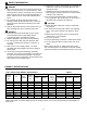
TROUBLESHOOTING Problem Possible Cause Corrective Action Little or no discharge 1. Casing not initially filled with water 1. Fill pump casing 2. Suction lift too high, or too long 2. Move pump closer to water source 3. Hole or air leak in suction line 3. Repair or replace. Use pipe tape and pipe sealing compound 4. Foot valve too small 4. Match foot valve to piping or install one size larger foot valve. 5. Foot valve or suction line not submerged deep 5.
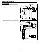
REPAIR PARTS FORM NO. FW0030 0712 SUPERSEDES 0109 CONVERTIBLE and SHALLOW WELL JET PUMP REPAIR PARTS “CPJ” and “CPJS” SERIES (For Pricing Refer To Repair Parts Price List) 1 15 10 2 4 6 5 SERVICE KIT FOR JET PUMPS 7 MODEL NO KIT CONTAINS KF011 Impeller, Diffuser, Rotary Seal, Quadraseal, Diffuser Rubber 8 13 KF022 KF033 KF164 KF045 9 3 IL0191 12 11 1. 2. 3. 4. Applies Applies Applies Applies VPH10 5.