
User guide

7 (FW1365)
95 North Oak St. • Kendallville, IN 46755 • 1-800-345-9422
IL1076
B2
B5
B4
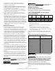
L1
L2
L3
U
V
W
PEPE
L1
L2
L3
U
V
W
PEPE
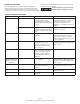
TABLE 5 DRIVE SPECIFICATIONS AND DIMENSIONS
Model Number ADW2W31 ADW2W51 ADW2W71 ADW2W73
Input from power
source
Voltage 180 - 264 ac Single or Three Phase Single Phase Three Phase
Frequency 50/60 Hz
Current (Max) - RMS
23.2 Amps 1ø
(11.9 Amps 3ø)
29.5 Amps 1ø
(15.7 Amps 3ø)
48.9 Amps 1ø 22.6 Amps 3ø
Power Factor 1.0 ( constant )
Output to Motor
(Three Phase )
Voltage Voltage Automatically Adjust with Frequency (0 thru 230 Volts)
Frequency Range 15 - 60 Hz
Current, Factory Programmed*
(RMS, Each Phase)
9.6 Amps 14.5 Amps 21.0 Amps 21.0 Amps
Current (Max)
(RMS, Each Phase)
9.6 Amps 15.0 Amps 22.0 Amps 22.0 Amps
For Use With
Motor Standard 60 Hz. Pump & 230 Volt 3 Phase Motor Combination
Reference HP Rating* 3 5 7.5 7.5
Pressure Setting
Factory preset 50 PSI
Adjustable Range 30 - 80 PSI
Operating
Conditions
Temperature
(@ 230 VAC input)
10° to 40° C ( 14° to 104° F. )
Relative Humidity Max 95% Non-condensing
RMS = ROOT MEAN SQUARED
* The electrical characteristics of motors vary slightly. See Amp draw on motor nameplate. If the maximum motor current value (Amp draw)
is more than 5% of the programmed value of the Drive, the Drive will need to be set to the current value of the motor to provide proper
protection..
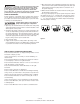
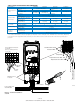
Mounting Screw
Locations
Power Supply from
Circuit Breaker
Power to Motor
GND
GND
Power Supply Connections
1ø shown
( for 3ø, connect power to
L1, L2, L3)
Pressure Sensor Leads
Figure 4 - Controller Installation
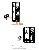
3 & 5 HP
Temperature Sensor Wire - Red
Temperature Sensor Wire - Black
Transducer Wire - Black
Transducer Wire - Red
Transducer Cable
Starter Control Wires
Temperature Sensor Cable
Jumper Wire
IL1140
B7B6B5
B4
B3B2
B1
T6T5T4T3T2T1
1
2
Power
Lines
Ground
Wires