Bend Sensor® Technology Mechanical Application Design Mechanical Application Guide Design Guide www.flexpoint.
Bend Sensor® Technology Mechanical Application Design Guide Contents Bend Sensor® Description 3 How the Bend Sensor® Potentiometer Works 4 Base Materials of the Bend Sensor® Product 5 Environmental Stability of Bend Sensor® Product 5 Base Resistance of Bend Sensor® Product 6 Effects of Radius of Curvature 6 Spring and Actuators 7 Various Spring Configurations 8 Properties of Spring Materials 9 Summary 10 www.flexpoint.
Bend Sensor® Mechanical Application Guide Introduction This Application Guide is designed to help mechanical designers build interfaces that result in the successful integration of Bend Sensor® components into products. Flexpoint Sensor Systems (Flexpoint) has successfully developed and marketed products incorporating Bend Sensor® technology. As described below the Bend Sensor® device is typically a film – the Bend Sensor® film is put into a system and essentially “goes along for the ride”.
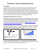
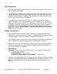
How the Bend Sensor® Potentiometer Works Flexpoint’s patented Bend Sensor® device consists of a single layer, thin, (0.005” typ.) flexible piece of material that is coated with a proprietary carbon/polymer based ink. This type of resistive element is commonly used to make thick film resistors, resistor networks, slide potentiometers and transducers. Flexpoint’s proprietary inks are primarily printed on thin plastic films.
The Bend Sensor® Device Base Materials – Can be printed on several substrates – is primarily printed on a plastic film such as polyimide. Contact the factory for the specifications on the materials used. The Bend Sensor® can be printed on both sides allowing the sensor to give readings in both directions and can delineate the direction of the bend as well as magnitude. The base material determines such factors as environmental stability, changes in resistance, durability, and costs.
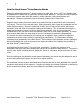
Base Resistance – Has a finite base resistance which, depending on geometry and design, can be as low as 100 Ω and as high as 500 KΩ. Its base (flat state) resistance is adjusted by changing the active geometry of the sensor – doubling the length will double the resistance or doubling the width halves the base resistance. Another method for adjusting base resistance is to add a conductive pattern over the sensor area to reduce the resistance.
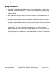
Spring and Actuator – It is critical to consider the fact that the sensor is typically attached to a moving device and simply “goes along for the ride.” The sensor has been attached to plastics, metals, rubbers, and other materials by means such as pressure sensitive adhesives, stitching, and heat staking. When attached to any other material the sensor takes on the mechanical properties of that material.
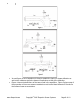
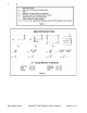
In each figure, a set of equations is found to predict the ’spring’ or beam deflection as well as the maximum stress the beam will experience at the given deflection. Figure 4 shows the definitions of the terms used in the equations. Figure 5 gives some of the properties of the more common materials as well as the Mass Moments of Inertia for the common beam cross sections. www.flexpoint.
www.flexpoint.
Summary: There are many methods that can accomplish the successful implementation of the Bend Sensor® product into an application. Further, it is important to consider the design of the electronic interface to be used with the sensors.