
User Manual

Maintenance
7
Slip clutch adjustment (continued)
Clutch adjustment, new type
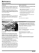
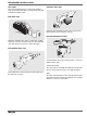
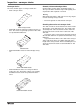
1 Remove the drive unit protection cover.
2 Use an Allen key, 3 mm, to loosen the screw (1) on the
slip clutch so that the adjustment nut (2) can be freely
rotated.
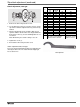
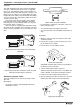
3 Turn the adjustment nut (2) clockwise with a hook
spanner until the arrow on the nut is aligned with the
desired F
max
value (3). See the following table for cor-
rect values.
Note: On delivery, the clutch is always set to “0”.
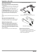
4 Tighten the screw (1).
5 Re-install the drive unit protection cover.
Clutch adjustment table, new type
F
max
is the desired maximum traction force applied to the
chain by the drive unit. The clutch will start slipping at
forces above F
max.
Hook spanner
1
2
3
No.
Traction force, F
max
(N)
XS
XL
XM, XH
XK, XB
XT XK H
0 300 300 300 600
1 400 400 400 800
2 500 500 500 1000
3 700 700 1150
4 800 800 1300
51550
6 1050 1050 1700
7
8 1250 1250 2000
9
10 1400 2200
11
12 1500 2400
13
14 1650 2500
Standard and direct drives 1/2”:
Slip clutches marked 3904324,
5052769, 3925774, 5052827
Standard drives 5/8”:
Slip clutches marked
3925071, 5052772