
User Manual

6
Maintenance
Slip clutch adjustment
Old and new versions
The slip clutch is available in two versions. Shipping of
the new version began in 2001. Adjustment of both ver-
sions are described here.
Introduction
The slip clutch on the drive unit is a safety device which
allows the chain to stop if the load becomes excessive. It
has two purposes:
• Prevent damage to conveyor
• Prevent damage to the products on the conveyor
Where a slip clutch is fitted, it must be adjusted so that it
does not slip whenever the drive unit is started under full
load. The installation is carried out as follows:
Preparations for adjustment
1 Stop the conveyor.
2 Ensure that the conveyor can not be started acciden-
tally. For example: unplug the electric power plug.
3 Remove any load on the conveyor.
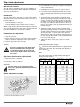
Caution:
If you try to adjust the slip clutch when
there is still load on the conveyor, the
accumulated tension in the chain can
cause severe injuries when you release
the clutch.
Slip clutch should not be adjusted until
1 Motor direction is confirmed
2 Conveyor is fully assembled
Important:
The slip clutch is not a personal safety
device. It is primarily intended to protect the
equipment.
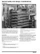
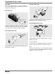
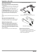
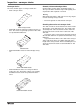
Clutch adjustment, old type
1 Remove the transmission cover.
2 Unscrew the three screws (8) so that the outer ring (7)
can be rotated freely.
3 Hand-tighten the outer ring (7) to stop (no tools!).
4 Look for the desired maximum traction force in the
table to the right and determine the X value for that
force.
5 Positive X-value: (If the X value is negative (X≤0)
ignore step 5 and go to step 6.) Turn the outer ring (7)
counter-clockwise the number of divisions given by
the table, i.e. the X value. One division is defined as
the angle (30°) between adjacent holes in the stop
ring (6). Check that screws (8) align with the holes in
the stop ring (6).
6 Negative X-value: (If the X value is positive (X≥0)
ignore step 6 and go to step 7.) Turn the outer ring (7)
clockwise with a hook wrench, the number of divisions
given by the table, i.e. the X value. One division is
defined as the angle (30°) between adjacent holes in
the stop ring (6). Check that screws (8) align with the
holes in the stop ring (6).
7 Tighten the three screws (8) to stop. Use 10 mm
wrench
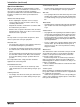
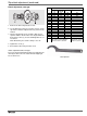
Clutch adjustment table, old type
F
max
is the desired maximum traction force applied to the
chain by the drive unit. The clutch will start slipping at
forces above F
max.
Note
The values in the table are approximate and apply to
factory-new slip clutches.
2
3
7
6
5
9
4
10
1
8
Traction force F
max
(N) X (div.) Traction force F
max
(N) X (div.)
XS
XL
XM
XH
XW
XK XM
XH
XW XK
450 450 100 19 1200 1200 1400 6
475 475 200 18 1300 1500 5
525 300 17 1400 1600 4
575 400 16 1525 1700 3
625 500 15 1800 2
675 600 14 1900 1
725 700 13 2000 0
775 800 12 2100 –1
825 900 11 2200 –2
875 1000 10 2300 –3
925 1100 9 2400 –4
1000 1200 8 2500 –5
1100 1300 7