
Manual
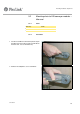
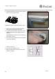
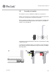
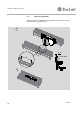
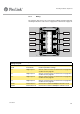
Table Of Contents
- Preface
- 1 Safety
- 2 Technical specification
- 3 Functions
- 4 Unload the X45 system
- 5 Mounting, installation, adjustment
- 6 Technical maintenance
- 7 Recommended spare parts
- 8 Supplier’s information
Mounting, installation, adjustment
Created by EBCCW 00:06
27
5113196-2
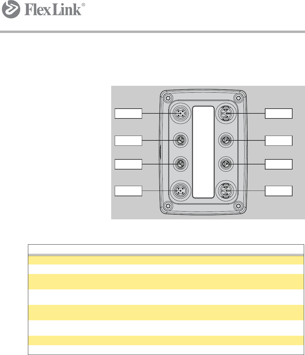
5.3.2 Wiring
The functions motors are to be connected according to picture below and
mounting instructions section 5.3.3 on page 28 to section 5.3.8 on page 32.
Markings on plate
Explanation
PWR Power in Connect power cable
BUS B Internal bus Used for parameter settings
DI 1 Digital input 1 Sensor, connect if used, see section 5.3.3 on page 28 to
section 5.3.8 on page 32
DI 2 Digital input 2 Sensor, connect if used, see section 5.3.3 on page 28 to
section 5.3.8 on page 32
DI 3 Digital input 3 Sensor, connect if used, see section 5.3.3 on page 28 to
section 5.3.8 on page 32
DI 4 Digital input 4 Sensor, connect if used, see section 5.3.3 on page 28 to
section 5.3.8 on page 32
BUS A1 External bus in Connect this if external CANOpen network is used
BUS A2 External bus out Connect this if external CANOpen network is used
BUS A1
DI 4
DI 2
PWR
BUS A2
DI 3
DI 1
BUS B
BUS A1
DI 4
DI 2
PWR
BUS B DI 1 DI 3 BUS A2
1