
User guide

Specification
Unit/Dept. Document type Date
APD/Research & Development
Assembly Instruction
2006-05-19
Issued by Document number Page Approved by
Fredrik Johansson 3928587-03 2/12 FJn
3928587_03.DOC
Archived
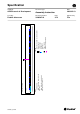
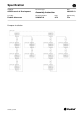
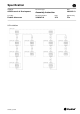
1. AGS-system layout
The AGS-system contains the following parts:
1. Control box;
2. Guide units;
3. Guide unit cables;
4. Junction box;
5. Zone supply cables.
The points 4 and 5 are used when the number of Guide units are higher than the Control
box itself can control.
The default distance between Guide units is 1 meter. This may be changed depending on
application.
See picture next page.
For more information see document "Controls overview".
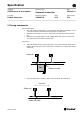
1.1 Integrator responsibility
Some parts of installation is application depending and part of the integrator’s
responsibility:
1. Box mounting frames;
2. Wire ways;
3. Zone supply conductors (see chapter “4. Zone supply”)