
User and installation manual


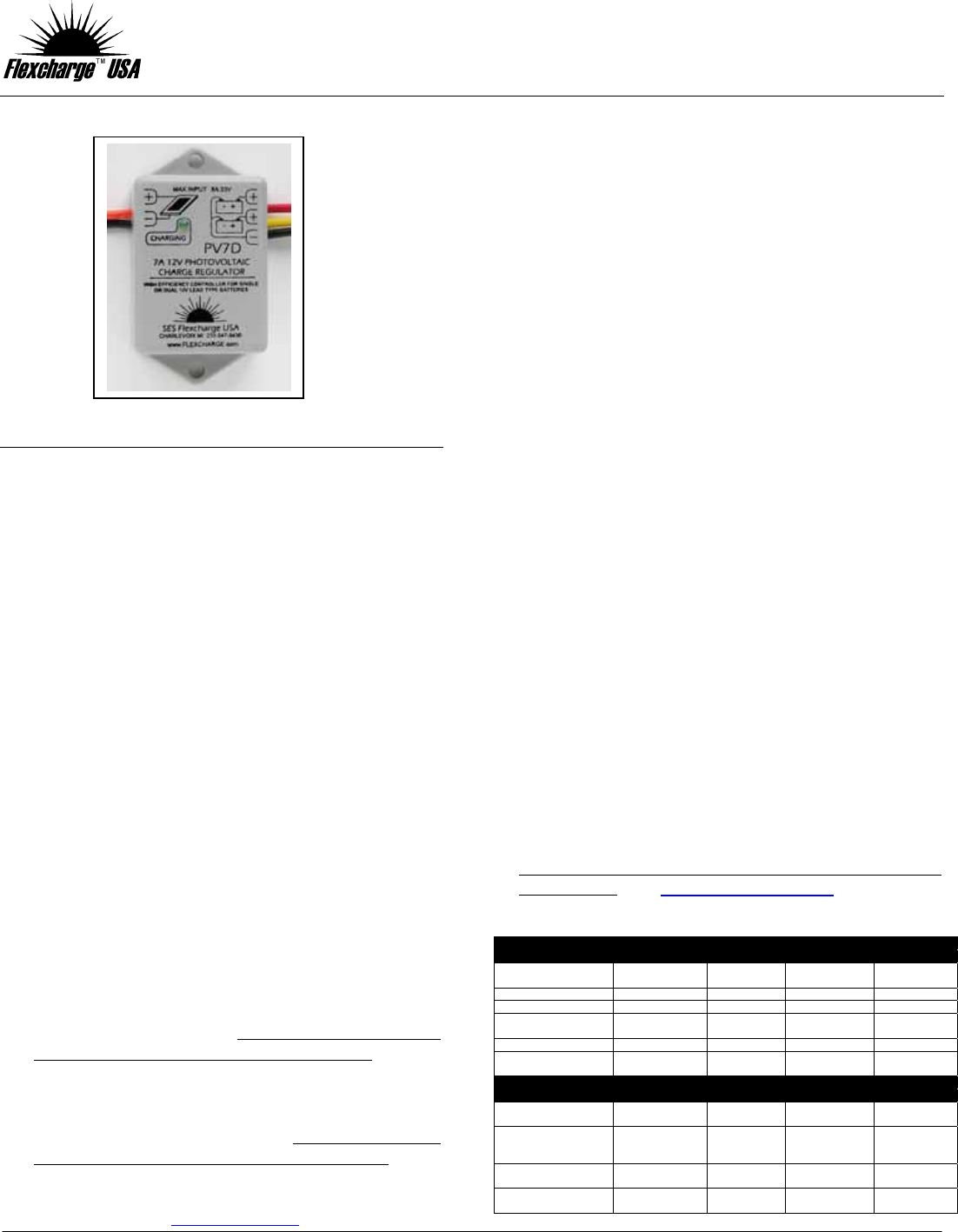
MODEL: PV7D (SHORT FORM)
7A 12V HIGH EFFECINECY DUAL BATTERY CHARGE CONTROLLER
SES Flexcharge USA, 1217 State St, Charlevoix, MI 49720
www.flexcharge.com Phone (231) 547-9430 Fax (231) 547-5522
INSTALLATION PROCEDURES
WORKS WITH FLOODED, GEL, AND AGM BATTERIES
PLAN AHEAD You will need the following items to finish the installation.
Red and Black Stranded & Tinned wire or cable. Size #14 or #16 AWG
(American Wire Gauge).
Proper wire connectors or soldering tools and mounting screws for
mounting the PV7D, and to make connections to battery and solar panel(s).
Connectors must not allow moisture to enter the connections.
Multi-meter to check the system operation (Optional).
General hand tools – Regular and Phillips screwdrivers and fixed or
adjustable wrench for battery terminals.
INSTALLATION STEPS
1. Mount the PV7D in a location where it will not get excessively warm or
be subject to high levels of vibration (not on an engine for example).
The PV7 should be located closer than 10 wired feet from the battery
bank. If fuse replacement is necessary, install an 8A fast blow fuse.
2. Connect PV7D to the battery bank. Start with the PV7D’s BLACK
BAT- wire and connect it to the Battery Bank’s negative terminal.
Next connect the PV7D’s RED BAT+ wire to the primary battery bank’s
positive terminal. If your battery installation is configured with a positive
and negative bus bar you may connect to them instead of the battery
posts. If you have a second battery bank connect the YELLOW wire to
the second battery bank positive. If there is only one battery use the
RED wire only or connect the RED and YELLOW together.
3. Connect the PV7D to the Solar panel. Connect the PV7D’s Black PV-
wire to the solar panel’s negative wire. Connect the PV7D’s ORANGE
PV+ wire to the solar panel positive wire. Do not operate with no
battery connected when the solar panels are producing power.
EXPANSION The PV7D can be expanded to hundreds of
amps. See our web site at www.flexcharge.com
TEST / VERIFICATION STEPS
GETTING READY TO TEST
1. Make sure the sun is shining on the entire solar panel (No part of the
panel is in the shade)
2. Ensure the ammeter is configured for measuring current and is set to
measure up to 10 Amperes.
TESTING (Optional)
1. Remove the PV7D’s fuse in the BLACK BAT+ wire.
2. Setup the Multi-meter to measure current (10A scale) and making
the measurement at the fuse holder, place one probe on the PV7D’s
BLACK BAT- wire and the other probe on the side of the fuse that is
connected to the battery bank NEGATIVE terminal.
3. With the PV7D’s green charge light ON, check to see that the
measured current is similar to what you would expect from the solar
panel.
4. Re-install the fuse. (Finished).
Note: If the battery is being charged from another source
(Alternator) the controller’s GREEN light may be OFF, meaning the
controller is fully regulating and not charging. The GREEN light
must be ON to test the PV7. If the green light is switching from ON
to OFF it means that the controller is REGULATING, ( in the final
stages of charging). Charging current will turn ON and OFF with the
green light.
You cannot check the open circuit output voltage of the controller.
Without a battery connected the voltage will be very low,(1 to 4
volts) and the green charge light will flash on and off at a fast rate.
A full length version of the PV7D manual is available at
our website. www.flexcharge.com
PV7D Specifications
A
BSOLUTE MAXIMUMS
Min Typ Max Units
Fuse
(Fast Blow)
- - 8 Amperes
Solar Panel Voltage 0 - 33 Volts
Battery Voltage 0 - 33 Volts
Operating
Temperature
-30°C (-22°F) - 50°C (122°F) Degrees
Storage Temperature -40°C (-40°F) - 55°C (131°F) Degrees
Humidity 2% 60%
100%
(Condensing)
Percent
OPERATING VALUES
Min Typ Max Units
Bat Voltage -
Charging
0 - 15.0 Volts
Bat Voltage-
Regulating
(Constantly Varies)
13.4
(Reconnect)
13.8
(Averaged)
15.0
(Disconnect)
Volts
Bat Voltage
(Not Charging)
0 12.6 - Volts
Charging Current 0
Solar Panel
Output
8 Amperes
Use on Solar Panels Only