
User's Manual

Connecting the Ante nna Cables
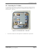
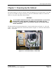
6.1. Connecting the Antenna Cables
1.
If they have not been rem oved already, remove the side access screw panels using a tamper
resistant insert hex bit. See Figure 3-2: Side Screw Panels.
2.
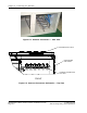
If they have not been re moved already, remove the outer pane l and sea l inse rts of the Roxtec
assembly on the rea r of the cabinet. See Figure 4-5: R oxtec Assembly.
3.
Route the antenna cable through the rectangular opening in the rear of the cabinet.
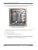
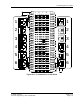
4.
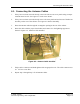
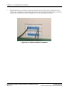
Route the c able with the proper be nd radius and conne ct it to the lightning suppressors
shown in Figure 6-3: Ante nna Cable Installed.
Figure 6-3: Antenna Cable Installed
5.
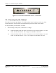
Fully seat the c onnec tor and hand tighten with an a ppropria te tool. The cable connector nut
is 1 1/4” he x across flats.
6.
Repeat Step 3 through Step 5 for all antenna ca bles.
© 2005 Flarion
Flarion Proprietary and Confidential
Version 1.3
Page 6-3