
User's Manual

Chapter 5: Connecting the Core Network Cables
3.
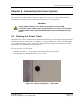
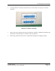
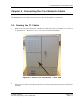
Insert the cables through the rectangular opening into the lower compartm ent of the cabinet.
4.
Route the cables through the internal cable clearance holes into the electronics compartment.
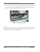
Figure 5-2: Cable Clearance Holes shows the clearance holes.
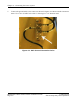
Figure 5-2: Cable Clearance Holes
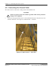
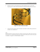
Note:
Reinstall the Rox tec seal inserts and outer panel after all of the system cables have been routed.
The seal inserts are installed tight against each cable and are held in p lace w hen the outer panel
is installed. See Figure 6-4: Cables Installed in Cabinet.
RadioRouter® Base Station Outdoor I nstallation Guide © 2005 Flarion
Flarion Proprietary and Confidential
Page 5-2