
User's Manual


Verifying the Site Preparation
Chapter 2. Verifying the Site Preparation
Before you begin the physica l installation of the base station, confirm that the site preparation
is comp lete. The chec klist that f o llows identifies the item s that m u st be in place before the
installation can begin. If any items are incomplete or missing, fill out the Punchlist in Appendix A
- Outdoor Base Station Site Preparation Punchlist.
2.1. Site Preparation Checklist — Outdoor Base Station
• Floor Plan
-
Architectural drawing or sketch of site indicating location of all equipm ent to be installed
including base station cabine t and cables
-
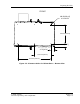
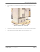
Floor plan with adequate space for cabinet — at least 24” front, 12” side, a nd 24” rea r
• Environment
-
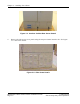
Cement slab for mounting cabinet
-
Temperature range −40 °C to 46 °C
• Electric al system
-
Split phase 240 VA C (120/240 VAC) or three- wire plus ground 240 VAC service
-
External Service Entrance with main breaker and surge suppressor
• Antenna plant
-
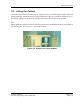
Mounting plate with a ntenna connectors
• T1 connection
-
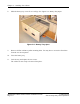
Network interf ace unit in the de ma rca tion point
-
T1 surge suppressor installed
• Cables
-
AC power cabling: #12 AWG or heavier. Sufficient length to reach base station plus 36”
-
Ground cabling t o ma ster ground bar: #6 to #2 AWG
-
RF cabling: Andrew 1/2” SuperFlex jum pers or equivalent. Sufficient length to rea ch base
station plus 24”. Color Code as described in Chapter 6. Connecting the Antennas.
-
T1 cabling: 100 ohm twisted pair cable, Beldin 9570 or equivalent. Sufficient length to
reach base station plus 36”.
© 2005 Flarion
Flarion Proprietary and Confidential
Version 1.3
Page 2-1