
User's Manual
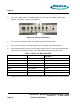
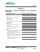

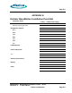

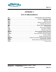
Table Of Contents
- toc
- Issue Date: 09- 23- 2003
- Overview
- 1.1. Installation Equipment
- Verifying the Site Preparation
- 2.1. Site Preparation Checklist •24 Outdoor BaseStation
- 2.2. Preparing the Floor
- Installing the Cabinet
- Connecting the Power System
- Connecting the Core Network Cables
- Connecting the Antennas
- Powering Up the Cabinet
- Powering Down the Cabinet
- Verifying the Installation
- RadioRouter Outdoor BaseStation Site Preparation Punchlist
- Outdoor BaseStation Installation Punchlist
- tables

Page A-1
APPENDIX A
RadioRouter Outdoor BaseStation Site Preparation
Punchlist
Site Preparation Items If Okay OR Describe Outage
Environment
Adequate Clearance: 24” front, 12” side, 24”
rear
Cement slab for mounting cabinet
Electrical system
240 VAC Service
External Service Entrance w/main breaker and
surge suppressor
Antenna plant
Mounting plate with antenna connectors
T1 connection
Network Interface Unit in Demarc point
Surge suppressor installed
Cables
AC power cabling: #12 AWG THHN or THWN
— length to reach cabinet plus 36”
Ground cabling to master ground bar: #6 to #2
AWG THHN or THWN
RF cabling — Andrews 1/2” SuperFlex jumpers
— length to reach cabinet plus 24”. Color
coded.
T1 cabling — 100 ohm twisted pair — length
to reach cabinet plus 36”
RadioRouter
®
BaseStation Installation Guide — Draft
Version 0.2 - © 2003 F larion
Flarion Confidential
Page A-1