
User's Manual
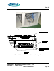
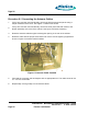
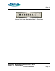
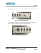
Table Of Contents
- toc
- Issue Date: 09- 23- 2003
- Overview
- 1.1. Installation Equipment
- Verifying the Site Preparation
- 2.1. Site Preparation Checklist •24 Outdoor BaseStation
- 2.2. Preparing the Floor
- Installing the Cabinet
- Connecting the Power System
- Connecting the Core Network Cables
- Connecting the Antennas
- Powering Up the Cabinet
- Powering Down the Cabinet
- Verifying the Installation
- RadioRouter Outdoor BaseStation Site Preparation Punchlist
- Outdoor BaseStation Installation Punchlist
- tables

Page 32
5.
Turn on the RRC breaker. The RRC breaker is to the right of the Battery Disconnect
breaker. See Figure 7.6 DC Circuit Breakers .
Figure 7.6 DC Circuit Breakers
6.
Turn on the LNA breakers which are located next to the RRC breaker.
7.
Turn on the PA breakers. The PA breakers are on the right of the LNA breakers.
8.
Verify that the LEDs on the front of the cabinet match Table 7.1 Power On Expected LEDs.
If the LEDs do not match the table, power the system down and check the wiring.
Table 7.1 Power O n Expected LEDs
Unit LED Name
Condition
PDU FAULT Green
PDU Service Green
PDU Fan Tray FAN Green
RRC FAN STATUS Green
RRC FAN STATUS Green
PCU1 ON (GREEN) FAIL (RED) Green
PCU2 ON (GREEN) FAIL (RED) Green
9.
Replace all side and rear panels using the original tamper resistant screws. Close all doors.
RadioRouter
®
BaseStation Installatio n Gu ide — Draft
Version 0.2 - © 2003 Flarion
Flarion Confidential
Page 32