
User's Manual
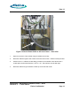
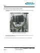
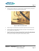
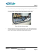
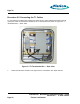
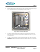
Table Of Contents
- toc
- Issue Date: 09- 23- 2003
- Overview
- 1.1. Installation Equipment
- Verifying the Site Preparation
- 2.1. Site Preparation Checklist •24 Outdoor BaseStation
- 2.2. Preparing the Floor
- Installing the Cabinet
- Connecting the Power System
- Connecting the Core Network Cables
- Connecting the Antennas
- Powering Up the Cabinet
- Powering Down the Cabinet
- Verifying the Installation
- RadioRouter Outdoor BaseStation Site Preparation Punchlist
- Outdoor BaseStation Installation Punchlist
- tables

Page 20
Procedure 5-2 Connecting the T1 Cables
T1 connections are made using a 66 punch down block or using cables terminated in RJ-48
connectors. Both connectors are located in the T1 termination box shown in Figure 5.3 T1
Termination Box — Rear View.
Figure 5.3 T1 Termination Box — Rear View
1.
Loosen the two latch screws on the right of the T1 termination box. Open the box.
RadioRouter
®
BaseStation Installatio n Gu ide — Draft
Version 0.2 - © 2003 Flarion
Flarion Confidential
Page 20