
User's Manual
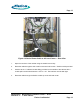
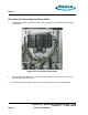
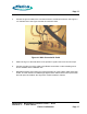
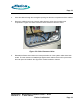
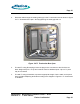
Table Of Contents
- toc
- Issue Date: 09- 23- 2003
- Overview
- 1.1. Installation Equipment
- Verifying the Site Preparation
- 2.1. Site Preparation Checklist •24 Outdoor BaseStation
- 2.2. Preparing the Floor
- Installing the Cabinet
- Connecting the Power System
- Connecting the Core Network Cables
- Connecting the Antennas
- Powering Up the Cabinet
- Powering Down the Cabinet
- Verifying the Installation
- RadioRouter Outdoor BaseStation Site Preparation Punchlist
- Outdoor BaseStation Installation Punchlist
- tables

Page 16
2.
Remove the outer panel and seal inserts of the Roxtec assembly. See Figure 4.5 Roxtec
Assembly. Additional information and instructions for the assembly are available on line
from Roxtec.
Figure 4.5 Roxtec Assembly
3.
Route the ground cable into the lower compartment through the rectangular opening.
RadioRouter
®
BaseStation Installatio n Gu ide — Draft
Version 0.2 - © 2003 Flarion
Flarion Confidential
Page 16