
User's Manual
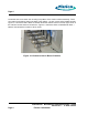
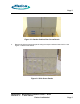
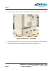
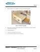
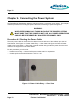
Table Of Contents
- toc
- Issue Date: 09- 23- 2003
- Overview
- 1.1. Installation Equipment
- Verifying the Site Preparation
- 2.1. Site Preparation Checklist •24 Outdoor BaseStation
- 2.2. Preparing the Floor
- Installing the Cabinet
- Connecting the Power System
- Connecting the Core Network Cables
- Connecting the Antennas
- Powering Up the Cabinet
- Powering Down the Cabinet
- Verifying the Installation
- RadioRouter Outdoor BaseStation Site Preparation Punchlist
- Outdoor BaseStation Installation Punchlist
- tables

Page 3
Chapter 2. Verifying the Site Preparation
Before you begin the physical installation of the RadioRouter BaseStation, confirm that the site
preparation is complete. The checklist that follows identifies all items that must be in place before
the installation can begin. If any items are incomplete or missing, fill out the Punchlist in Appendix
A - RadioRouter Outdoor BaseStation Site Preparation Punchlist.
2.1. Site Preparation Checklist — Outdoor BaseStation
• Floor Plan
-
Architectural drawing or sketch of site indicating location of all equipment to be installed
including base station cabinet and cables.
-
Floor plan allows adequate space for cabinet — at least 24” front, 12” side, and 24” rear
• Environment
-
Cement slab for mounting cabinet
-
Temperature range −40 Cto46C
• Electrical system
-
Split phase 240 VAC (120/240 VAC) or three-wire plus ground 240 VAC service
-
External Service Entrance with main breaker and surge suppressor
• Antenna plant
-
Mounting plate with antenna connectors
• T1 connection
-
Network interface unit i n the demarcation point
-
T1 surge suppressor installed
• Cables
-
AC power cabling: #12 AWG or heavier. Sufficient length to reach base station plus 36”.
-
Ground cabling to master ground bar: #6 to #2 AWG
-
RF cabling: Andrews 1/2” SuperFlex jumpers or equivalent. Sufficient length to reach base
station plus 24”. Color Code as described in Chapter 6. Connecting the Antennas.
-
T1 cabling: 100 ohm twisted pair cable, Beldin 9570 or equivalent. Sufficient length to reach
base station plus 36”.
2.2. Preparing the Floor
A concrete slab at the outdoor base station location must be provided for mounting. Install
concrete anchors in the slab for 3/8” size bolts, 1” minimum length. Use corrosion resistant
anchors.
RadioRouter
®
BaseStation Installation Guide — Draft
Version 0.2 - © 2003 F larion
Flarion Confidential
Page 3