
User's Manual

Chapter 8: Powering Up the Cabinet
2.
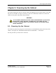
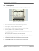
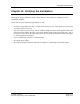
Turn on the RRC bre aker. The RR C br eake r is on the left as you fac e the cabinet. See
Figure 8-3: Circuit Breakers — Front View and Figure 8-4: Circuit Breakers Schematic
— Front View .
Figure 8-3: Circuit Breakers — Front View
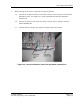
Figure 8-4: Circuit Breakers Schematic — Front View
3.
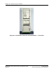
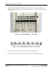
Turn on the LNA breakers which a re located next to the R RC breake r.
4.
Turn on the PA breakers. The PA breakers are on the right of the LNA breakers.
RadioRouter Base Station Indoor Installation Guide © 2005 Flarion
Flarion Proprietary and Confidential
Page 8-4