
User's Manual

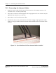

Chapter 7: Conne cting the Antenna Cables
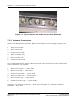
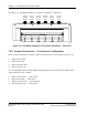
See Figure 7-5: Top-Mount Antennas, 6–Connector Schematic — Rear View.
ALPHA
SECTOR
TX/RX
BETA
SECTOR
TX/RX
GAMMA
SECTOR
TX/RX
ALPHA
SECTOR
RX ONLY
BETA
SECTOR
RX ONLY
GAMMA
SECTOR
RX ONLY
Figure 7-5: Top-Mount Antennas, 6–Connector Schematic — R ear View
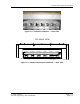
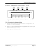
7.2.2. Antenna Connectors — 4–Connector Configuration
There are four DIN Female connec tors. When viewed from the rear from right to left,theyare:
1. Alpha se ctor Tx/Rx
2. Beta sector Tx/R x
3. Alpha sector RX only
4. Beta sector R x only
It is recomm ended that the antenna cables that attach to the connectors be c lear ly labeled with
color-coded bands. For exa mple:
1. Alpha sector Tx/Rx — 1 white band
2. Beta sector Tx/Rx — 1 blue band
3. Alpha sector R X only — 2 white bands
4. Beta sector Rx only — 2 blue bands
RadioRouter Base Station Indoor Installation Guide © 2005 Flarion
Flarion Proprietary and Confidential
Page 7-6