
User's Manual


Systems with Top Mounted Connectors
7.2. Systems with Top Mo unted Co nne cto rs
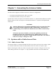
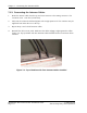
In some systems, the antenna c ables are a ttache d to connec tors located at the top of the base
station. Typically, there are either four or six connectors. Figure 4-6: Top-Mount Antenna
Connectors — Re ar View shows the location of the connectors.
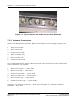
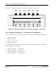
7.2.1. Antenna Connectors — 6–Connector Configuration
There ar e six DIN Fem ale connectors. Whe n viewe d from the rear from right to left,theyare:
1. Alpha sector Tx/Rx
2. Beta sector Tx/Rx
3. Gamm a sector Tx/Rx
4. Alpha sector RX only
5. Beta sector Rx only
6. Gamm a sector Rx only
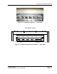
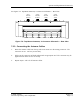
It is recom me nded that the antenna cables t hat attach to the connectors be clearly labeled with
color-coded bands. For example:
1. Alpha sec tor Tx/Rx — 1 white band
2. Beta sector Tx/Rx — 1 blue band
3. Gamma sector Tx/Rx — 1 green band
4. Alpha sector RX only — 2 w hite bands
5. Beta sector R x only — 2 blue bands
6. Gamm a sector Rx only — 2 green bands
© 2005 Flarion
Flarion Proprietary and Confidential
Version 1.7
Page 7-5