
User's Manual


Customer Definable A larm Inputs
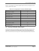
Table 6- 2: Pin Assignments for Customer Definable Outputs show s the pin assignments for the
customer definable alarm outputs.
Table 6-2: P in Assignments for Customer Definable O utputs
Connection Pin Assignment
Alarm Output 1: Common 4
Alarm Output 1: N/O 5
Alarm Output 1: N/C 6
Alarm Output 2: Common 7
Alarm Output 2: N/O 8
Alarm Output 2: N/C 9
Alarm Output 3: Common 29
Alarm Output 3: N/O 30
Alarm Output 3: N/C 31
Alarm Output 4: Common 32
Alarm Output 4: N/O 33
Alarm Output 4: N/C 34
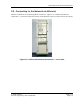
6.4. Cus tom er Definable Alarm Inputs
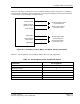
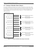
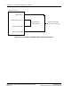
The ba se station m onitors the alarm inputs for e x ternal dry contact closures. Each e xterna l dry
contact must be c onnecte d a cross the Alarm Input pin and the Alarm Voltage Supply pin. A
connection is a lso re quired between the Alarm Return pin and the Alarm Voltage Re turn pin.
These two connections are shown in Figure 6-5: Customer Definable Alarm Input Connections.
© 2005 Flarion
Flarion Proprietary and Confidential
Version 1.7
Page 6-5