
User's Manual


Chapter 6: Installing the Alarm Connections
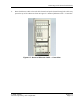
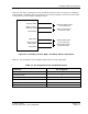
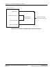
6.3. Custom er Definable Alarm Outp uts
The customer definable ala rm outputs use dry contacts. C onnec t ions are m ade to these a larms
by attaching the exter nal device between the desired ala rm pin and its associate d c ommon alarm
pin. Connections can be made to Normally Open ( N/O) or to Norm ally Closed (N/C) pins. The
Customer definable alarm connec tions are shown in Figure 6-4: Customer De finable Alarm
Output Connections.
Alarm Output 1 N/O
Alarm Output 1 Common
Alarm Output 1 N/C
AIU RTB EXT Connector
Alarm Output 2 N/O
Alarm Output 2 Common
Alarm Output 2 N/C
Alarm Output 3 N/O
Alarm Output 3 Common
Alarm Output 3 N/C
Alarm Output 4 N/O
Alarm Output 4 Common
Alarm Output 4 N/C
Monitor Normally Open Alarm Output 1
across these pins
Monitor Normally Closed Alarm Output 1
across these pins
Monitor Normally Open Alarm Output 2
across these pins
Monitor Normally Closed Alarm Output 2
across these pins
Monitor Normally Open Alarm Output 3
across these pins
Monitor Normally Closed Alarm Output 3
across these pins
Monitor Normally Open Alarm Output 4
across these pins
Monitor Normally Closed Alarm Output 4
across these pins
Figure 6-4: Customer Definable Alarm Output Con nections
RadioRouter Base Station Indoor Installation Guide © 2005 Flarion
Flarion Proprietary and Confidential
Page 6-4