
User's Manual

Chapter 4: Connecting the Power System
2.
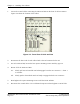
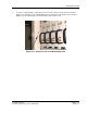
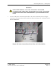
Route the cable through the channel to the lower portion of the cabine t. See Figure 4-3:
Cable R outed in C hanne l.
Figure 4-3: Cable Routed in Channel
3.
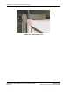
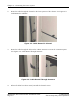
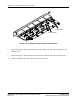
Route the cable through the hole s in the cabinet structure to access the connection point.
See Figure 4-4: Cable Routed Through Structure.
Figure 4-4: Cable Routed Through Structure
4.
When a ll cables have b ee n routed, reinstall the channel covers.
RadioRouter Base Station Indoor Installation Guide © 2005 Flarion
Flarion Proprietary and Confidential
Page 4-4