
User's Manual

Verifying the Site Preparation
Chapter 2. Verifying the Site Preparation
Before you begin the physical installation of the base station, confirm that the site preparation is
complete. The chec klist below identifies all items that must be in place before the installation
can begin.
WARNING:
IF PROPER SURGE ARR ESTORS ARE NOT IN PLACE, DAMAGE TO
THE EQUIPMENT MAY RESULT.
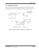
2.1. Site Preparation Checklist — I ndo or Bas e Station
• Floor Plan
-
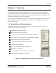
Architectural drawing or sketch of site indica ting location of all equipme nt to be installed,
including base station cabine t and cables
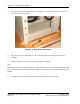
• Environment
-
Enclosed space with functional H VAC
-
Floor plan with a dequate space for c abinet — at least 24” front and 6” rear
• Electric al system
-
Appropriate pow er f eeds and surge suppression
-
Approriate site grounding, for example internal gr ound halo and master ground bar
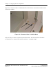
• Antenna plant
-
Surge arr estor mounting available , arrestor i nstalled
-
Six Tx/Rx a ntenna line surge protectors installed on surge arrestor mounting
• Backhaul connection
-
Backhaul surge arrestor m ounting available, arrestor installed
-
Surge arre stor grounded and re ady to b e connec ted to backhaul networ k termi nation
• Alarm connection
-
One AC power failure alarm termination point — AMP 554954–2 connector
-
One high temperature a larm termination point — AMP 554954–2 connector
• Cable support
-
Trays or other support m ec hanisms for cables available
• Cables
-
DC power ca bling: #6 AWG THHN or THWN
-
Ground cabling to m aster ground bar: #6 AWG TH H N or THWN
-
RF cabling to surge arrestors: Andrews 1/2” SuperFlex jumpers or equivalent
© 2005 Flarion
Flarion Proprietary and Confidential
Version 1.7
Page 2-1