
User's Manual
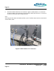
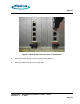
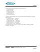
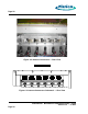
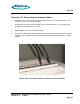
Table Of Contents
- toc
- Issue Date: 08- 04- 2003
- Overview
- Verifying the Site Preparation
- 2.1. Site Preparation Checklist •24 Indoor BaseStation
- 2.2. Preparing the Floor
- Installing the Cabinet
- Connecting the Power System
- 4.1. Routing the Cables
- 4.2. Connecting to Power and Ground
- Connecting the Core Network Cables
- Connecting the Antennas Cables
- Installing the Alarm Connections
- Powering Up the Cabinet
- Powering Down the Cabinet
- Verifying the Installation
- 10.1. Verifying the Physical Installation
- 10.2. Verifying the Base Station Operation
- RadioRouter BaseStation Site Preparation Punchlist
- RadioRouter BaseStation Installation Punchlist
- tables

Page 27
There are six Din Female connectors. From right to left they are:
1. Alpha sector Tx/Rx
2. Beta sector Tx/Rx
3. Gamma sector Tx/Rx
4. Alpha sector RX only
5. Beta sector Rx only
6. Gamma sector Rx only
The antenna cables that attach to the connectors should be clearly labeled with color-coded
bands as follows:
1. Alpha sector Tx/Rx — 1 white band
2. Beta sector Tx/Rx — 1 blue band
3. Gamma sector Tx/Rx — 1 green band
4. Alpha sector RX only — 2 white bands
5. Beta sector Rx only — 2 blue bands
6. Gamma sector Rx only — 2 green bands
See Figure 6.2 Antenna Connectors — Rear View and Figure 6.3 Antenna Connectors
Schematic — Rear View
RadioRouter
®
BaseStation Installation Guide — Draft
Version 0.5 - © 2003
Page 27