
User's Manual
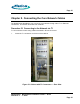
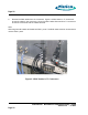
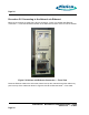
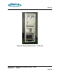
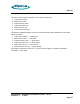
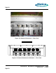
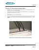
Table Of Contents
- toc
- Issue Date: 08- 04- 2003
- Overview
- Verifying the Site Preparation
- 2.1. Site Preparation Checklist •24 Indoor BaseStation
- 2.2. Preparing the Floor
- Installing the Cabinet
- Connecting the Power System
- 4.1. Routing the Cables
- 4.2. Connecting to Power and Ground
- Connecting the Core Network Cables
- Connecting the Antennas Cables
- Installing the Alarm Connections
- Powering Up the Cabinet
- Powering Down the Cabinet
- Verifying the Installation
- 10.1. Verifying the Physical Installation
- 10.2. Verifying the Base Station Operation
- RadioRouter BaseStation Site Preparation Punchlist
- RadioRouter BaseStation Installation Punchlist
- tables

Page 24
Procedure 5-2 Connecting to the Network via Ethernet
Ethernet connections are made using RJ-45 connectors. Figure 5.4 Cabinet with Ethernet
Connection — Front View shows the location of the Ethernet connector on the front of the cabinet.
Figure 5.4 Cabinet with Ethernet Connection — Front View
Route the Ethernet cable to the side cable channel and up the channel through the cable entry
port in the top of the cabinet as shown in Figure 5.5 Route of Ethernet Cable — Front View.
RadioRouter
®
BaseStation Installation Guide — Draft
Version 0.5 - © 2003
Page 24