
User's Manual
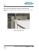
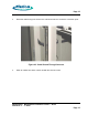
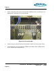
Table Of Contents
- toc
- Issue Date: 08- 04- 2003
- Overview
- Verifying the Site Preparation
- 2.1. Site Preparation Checklist •24 Indoor BaseStation
- 2.2. Preparing the Floor
- Installing the Cabinet
- Connecting the Power System
- 4.1. Routing the Cables
- 4.2. Connecting to Power and Ground
- Connecting the Core Network Cables
- Connecting the Antennas Cables
- Installing the Alarm Connections
- Powering Up the Cabinet
- Powering Down the Cabinet
- Verifying the Installation
- 10.1. Verifying the Physical Installation
- 10.2. Verifying the Base Station Operation
- RadioRouter BaseStation Site Preparation Punchlist
- RadioRouter BaseStation Installation Punchlist
- tables

Page 20
2.
Connect the ground cable to the connectors with 6 AWG wire with a 2–hole lug for a 1/4”
diameter stud. SeeFigure 4.10 Ground Bus B ar.
Figure 4.10 Ground Bus Bar
3.
Fasten the lug on to the stud with the nuts provided. Tighten nuts to 40–50 in-lb torque.
4.
Connect the other end of the c able to the Master Ground Bar or other suitable ground
source available at the installation site.
RadioRouter
®
BaseStation Installation Guide — Draft
Version 0.5 - © 2003
Page 20