
User's Manual
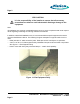
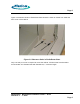
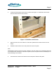
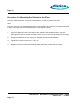
Table Of Contents
- toc
- Issue Date: 08- 04- 2003
- Overview
- Verifying the Site Preparation
- 2.1. Site Preparation Checklist •24 Indoor BaseStation
- 2.2. Preparing the Floor
- Installing the Cabinet
- Connecting the Power System
- 4.1. Routing the Cables
- 4.2. Connecting to Power and Ground
- Connecting the Core Network Cables
- Connecting the Antennas Cables
- Installing the Alarm Connections
- Powering Up the Cabinet
- Powering Down the Cabinet
- Verifying the Installation
- 10.1. Verifying the Physical Installation
- 10.2. Verifying the Base Station Operation
- RadioRouter BaseStation Site Preparation Punchlist
- RadioRouter BaseStation Installation Punchlist
- tables

Page 5
Figure 2.2 Clearance Holes in RadioRouter Base shows the holes as viewed from inside the
front corner of the cabinet.
Figure 2.2 Clearance Holes in RadioRouter Base
Only one hole per corner is required to mount the cabinet. All holes must have threads to
accommodate 1/2” diameter bolts with flat washers, 1” minimum length.
RadioRouter
®
BaseStation Installation Guide — Draft
Version 0.5 - © 2003
Page 5