
User's Manual
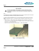
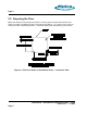
Table Of Contents
- toc
- Issue Date: 08- 04- 2003
- Overview
- Verifying the Site Preparation
- 2.1. Site Preparation Checklist •24 Indoor BaseStation
- 2.2. Preparing the Floor
- Installing the Cabinet
- Connecting the Power System
- 4.1. Routing the Cables
- 4.2. Connecting to Power and Ground
- Connecting the Core Network Cables
- Connecting the Antennas Cables
- Installing the Alarm Connections
- Powering Up the Cabinet
- Powering Down the Cabinet
- Verifying the Installation
- 10.1. Verifying the Physical Installation
- 10.2. Verifying the Base Station Operation
- RadioRouter BaseStation Site Preparation Punchlist
- RadioRouter BaseStation Installation Punchlist
- tables

Page 3
Chapter 2. Verifying the Site Preparation
Before you begin the physical installation of the RadioRouter BaseStation, confirm that the site
preparation is complete. The checklist that follows identifies all items that must be in place
before the installation can begin. If any items are incomplete or missing, fill out the Punchlist in
Appendix A - RadioRouter BaseStation Site Preparation Punchlist.
2.1. Site Preparation Checklist — Indoor BaseStation
• Floor Plan
-
Sketch of site indicating location of all equipment to be installed including base s tation cab-
inet and cables.
• Environment
-
Enclosed space with functional HVAC
-
Floor plan allows adequate space for cabinet — at least 24” front and 6” rear
• Electrical system
-
Load center, transfer switch, electrical outlets, and feeds for rectifiers available
-
Internal ground halo and master ground bar available
• Antenna plant
-
Surge arrestor mounting available
-
Six Tx/Rx antenna line surge protectors installed on surge arrestor mounting
• T1 connection
-
T1 surge arrestor installed
-
Surge arrestor grounded and ready to be connected to T1 network termination
• Alarm connection
-
One AC power failure alarm termination point — AMP 554954–2 connector
-
One high temperature alar m termination point — AMP 554954–2 connector
• Cable Support
-
Trays or other support mechanisms for cables available
• Cables
-
DC power cabling: #6 AWG THHN or THWN
-
Ground cabling to master ground bar : #6 AWG THHN or THWN
-
RF cabling to surge arrestors: Andrews 1/2” SuperFlex jumpers or equivalent
-
T1 cabling: 2–pair shielded
-
Alarm sensor cables
RadioRouter
®
BaseStation Installation Guide — Draft
Version 0.5 - © 2003
Page 3