Index Note: Before beginning you must first measure the width of your front end from LEFT outer tie rod end zerk fitting to the RIGHT outer tie rod end zerk fitting to determine the overall width of you front end. Write dimension here for further reference. Note: A front end alignment is necessary after installation. Note: Hoses (FR1625) and Hazard Wiring Kits are sold separately and are not included in this kit.
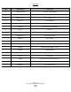
. Inventory Qty Part Number Description 5 C-BOLT-3/8-16X4 3/8"-16 X 4" Carriage Bolt 5 WASH-3/8 3/8" Flat Washers 5 NYLOCK-3/8-16 3/8" -16 Nylock nuts 3 WASH-1/2" 1/2" Flat Washers 2 NUT-5/8-18 5/8"-18 Jam Nuts 1 TRIPMPB1 Power Steering Pump Bracket 1 FR1614 Reservoir 1 FRPMPSB-V P/S Pump V-Belt 1 FR20101-57 Column Floor Mount 1 FR20118 Wiring Adapter 1 FR1934 1"DD X 3/4DD Chrome MolyU-Joint 1 FR1920 3/4DD X 3/4DD Chrome Moly U-Joint 1 FR1789P 3/4DD X FR Power Bille
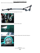
Removal of Original Steering System 1) Begin by removing the outer tie rod ends from the spindles. This is done by removing the cotter pin and castle nut and separating the tie rod end from the spindle using a pickle fork. 2) Remove the nut that retains the pitman arm to the sector shaft of the steering gear box. 3) Using a pitman arm puller, remove the pitman arm from the steering gear box. 4) Remove the two (2) bolts that hold the idler arm to the frame rail.
Removal of Original Steering System Con’t 5) Remove the entire steering linkage assembly from the car. 6) On column shift columns, disconnect the shift linkage from the column. 7) Remove the two (2) screws from the back side of the steering wheel. 8) Remove the three screws that hold the horn ring to the steering wheel and the wheel retaining nut.
Removal of Original Steering System Con’t 9) Using the two holes and a steering wheel puller, remove the wheel from the column. 10) Remove the lower dash shroud by removing the one (1) screw in the middle. 11) Remove the two (2) screws that hold the lower dash shroud mount in place, and then remove the mount.
Removal of Original Steering System Con’t 12) Remove the column wiring for the turn signal switch and the neutral safety switch (column shift only) from under the dash. Color Verification to be completed before disassembly Brake Light Switch RR Turn Signal LR Turn Signal Turn Signal Power Hazard Power RF Turn Signal LF Turn Signal Horn 13) Remove the two bolts that retain the column mount to the dash. 14) Remove the factory floor seal.
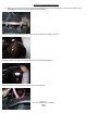
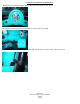
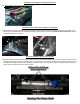
Removal of Original Steering System Con’t 16) Pivot the column downward and remove the column from the box shaft. Then remove the box from the car. Installation of Flaming River Steering Column 1) Remove pivot ball (black arrow with dotted line) from assembly by removing the two socket head screws seen in picture with the white arrow. Next slide the pivot ball over the column tube and then place the main body of the assembly over the pivot ball and lightly snug the two socket head screws (white arrow).
Installation of Flaming River Steering Column Con’t 3) Replace the lower dash shroud mounting bracket using the screws that were removed earlier. 4) Replace the lower dash shroud using the screw that was removed earlier. 5) Install the jumper harness by plugging the corresponding ends to the column and to the factory harness according to the instructions provided with the wiring kit.
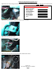
Installation of Flaming River Steering Column Con’t 6) Column Shift Only: Plug in the neutral safety switch Installation of the Power Rack and Pinion Cradle System 1) Slide the Rack and Pinion Cradle Assembly in-between the frame rails and insert the (3) mounting bolts on the driver’s side and the (2) on the passenger side. Install support bearing and bracket on the rear bolt (white arrow with dotted line). Tighten mounting hardware to 40- 45ft lbs.
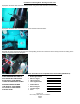
Power Rack & Pinion Universal Joint System Con’t Note: The angle of the support bearing mount is set for most applications. Some adjustment may be necessary for the correct angle and u-joint alignment 2). We recommend the use of ¾” dowel rod to mock up the steering shaft to obtain the correct length of the shafts. Install your shaft kit and snug each set screw so that it will leave a mark in the shafts. 3) Remove shaft and dimple each setscrew mark using a ¼” drill bit. (As shown above.
Bleeding the System 1) Raise the front wheels off the ground and support vehicle on jack stands. 2) Turn the wheel to the left lock and fill the reservoir with high-quality power steering fluid and allow vehicle to sit for 2 minutes. 3) With the engine off and someone checking the fluid level rotate the steering wheel lock to lock 20 times filling with fluid as necessary. 4) With the engine running, rotate the steering wheel back and forth from lock-to-lock. Repeat several times.