
Integration Manual


FLC-BTMDC746 Specification
Flaircomm Technologies Confidential
12
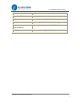
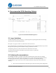
5. Recommended PCB Mounting Pattern
Figure 3 Recommended PCB Mounting Pattern
5.1 Layer Guidelines
To obtain the optimal system performance, a system integrator incorporating this module into the design
should follow the following PCB guidelines:
Do not place any copper or metal near, underneath or above the antenna.
Place ground sticking vias around the edges of the ground copper pours and the board outline to prevent the
RF signal from penetrating into the PCB board causing unintentional resonators.
Avoid placing plastic or any dielectric material closer than 5mm to the antenna.
Any metal placed should be at least 20mm away from the antenna in any direction.
Avoid copper trace loops.
5.2 Soldering Recommendations
FLC-BTMDC746 module is compatible with industrial standard reflow profile for Pb-free soldering
process, while the actual profile used in reflowing the entire system incorporating the module depends on
the thermal mass of the entire components populated on such system. The following soldering
recommendations are given below to ensure the reliable solder joints and operation of the module after
soldering:
Refer to the technical documents of the solder paste used for the reflow profile configurations.