
User's Manual

FLC-CBM202 Datasheet
Flaircomm Microelectronics Confidential
-21-
Generating these signals by DDS from CBM202 internal 4MHz clock. Using this mode limits
PCM_CLK to 128, 256 or 512 kHz and PCM_SYNC to 8 kHz.
Generating these signals by DDS from an internal 48MHz clock (which enables a greater range
of frequencies to be generated with low jitter but consumes more power). To select this second
method set bit 48M_PCM_CLK_GEN_EN in PSKEY_PCM_CONFIG32. When in this mode
and with long frame sync, the length of PCM_SYNC is either 8 or 16 cycles of PCM_CLK,
determined by LONG_LENGTH_SYNC_EN in PSKEY_PCM_CONFIG32.
The equation below describes PCM_CLK frequency when generated from the internal 48MHz clock:
24MHz
CNT_LIMIT
CNT_RATE
f
Set the frequency of PCM_SYNC relative to PCM_CLK using:
8SYNC_LIMIT
PCM_CLK
f
CNT_RATE, CNT_LIMIT and SYNC_LIMIT are set using SKEY_PCM_LOW_JITTER_CONFIG.
As an example, to generate PCM_CLK at 512 kHz with PCM_SYNC at 8 kHz, set
SKEY_PCM_LOW_JITTER_CONFIG to 0x08080177.
4.6.1.3 PCM Configuration
Configure the PCM by using the PS Keys, PSKEY_PCM_CONFIG32 and
SKEY_PCM_LOW_JITTER_CONFIG, see your PS Key file. The default for
SKEY_PCM_CONFIG32 is 0x00800000, i.e. first slot following sync is active, 13-bit linear voice
format, long frame sync and interface master generating 256 kHz PCM_CLK from 4MHz internal
clock with no tristate of PCM_OUT.
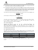
4.6.2 Digital Audio Interface (I²S)
The digital audio interface supports the industry standard formats for I²S, left-justified or right-
justified. The interface shares the same pins as the PCM interface, which means each audio bus is
mutually exclusive in its usage. Table below lists these alternative functions.
PCM Interface
I²S Interface
PCM_OUT
SD_OUT
PCM_IN
SD_IN
PCM_SYNC
WS
PCM_CLK
SCK
Table 4: PCM and I
2
S Digital Audio Interface
Configure the digital audio interface using the PSKEY_DIGITAL_AUDIO_CONFIG, see your PS
Key file.