
User's Manual

FLC-CBM202 Datasheet
Flaircomm Microelectronics Confidential
-15-
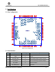
4. Physical Interfaces
4.1 WiFi Power Supply
4.1.1 Linear Regulator for Digital Supply
A 1.2V LDO in CBM202 powers the core digital circuits and WiFi_VREG_IN_DIG1.8V(Pin17) is
the input voltage. The range of this voltage is from 1.45V to 2.0V. WiFi_VDD_DIG (Pin19) is the
output of this LDO. A low ESR 2.2uF and a 10nF capacitors to ground should be connected to this
pin.
4.1.2 Linear Regulator for Analogue Supply
Three 1.2V LDO are built in CBM202 to power WiFi core auxiliary, radio and RF synthesizer.
WiFi_VREG_IN_ANA1.8V (Pin30) is the input voltage. The range of this voltage is from 1.45V to
2.0V.
4.1.3 RF Front End Power Supply
WIFI_VDDRF3.3V (Pin37) is the external 3.3V input to power WiFi+BT RF front end. Clean
voltage should be used and a 1.0uF bypass cap should connect to this pin.
4.1.4 I/O Power Supply
WIFI_VDDIO (Pin20) is used to power WiFi PIO[0] to WiFi PIO[7]. The typical voltage is
1.8V for this rail.
WIFI_VDDAIO3.3V (Pin28) is used to power WiFi PIO[8] to WiFi PIO[15], WiFi AIO[0] to
WiFi AIO[3]. Typical voltage is 3.3V for this rail.
4.2 BT Power Supply
There are three LDOs are used in the CBM202 module for BT circuits. BT_1.8V (Pin15) is the
input voltage for these LDOs.
One LDO is used to power the BT core digital circuits. BT_VDD_DIG (Pin16) is the output of
the LDO. An external low ESR minimum 1.5F capacitor must be connected to this pin.
One LDO is used to power BT radio circuits. BT_VDD_RF (Pin4) is the output of the LDO. An
external low ESR minimum 1.5F capacitor must be connected to this pin.
One LDO is used to power BT aux circuits. BT_VDD_AUX (Pin3) is the output of the LDO.
An external low ESR minimum 470nF capacitor must be connected to this pin.
BT_VDDIO (Pin5) is external 1.8V power supply to power all BT IO port including all GPIOs,
UART and PCM ports.
4.3 Reset
WiFi and BT of FLC-CBM202 can be reset individually from several sources.