
User's Manual


FLC-BTM403 Datasheet
Flaircomm Microelectronics Confidential
-4-
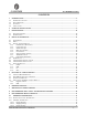
10.2.4 Product Grade ............................................................................................................................................. 33
11. CAUTIONS &WARNINGS ............................................................................................................................ 35
11.1 FCC STATEMENT ................................................................................................................................................ 35
11.2 FCC RADIATION EXPOSURE STATEMENT ........................................................................................................... 35
11.3 FLC-BTM403 LABEL INSTRUCTIONS ................................................................................................................. 35
11.4 FLC-BTM403 ANTENNA STATEMENT ................................................................................................................ 36
11.4.1 BTM403A and BTM403C ......................................................................................................................... 36
11.4.2 BTM403B .................................................................................................................................................. 38
TABLES AND FIGURES
Table 1: Naming Declaration ........................................................................................................................................... 6
Table 2: General Specification ......................................................................................................................................... 9
Table 3: Pin Definition ................................................................................................................................................... 11
Table 4: Pin Status on Reset ........................................................................................................................................... 12
Table 5: PCM Master Timing ........................................................................................................................................ 18
Table 6: PCM Slave Timing ........................................................................................................................................... 20
Table 7: Possible UART Settings ................................................................................................................................... 22
Table 8: USB Interface Component Values ................................................................................................................... 23
Table 9: Absolute Maximum Rating Recommended Operating Conditions .................................................................. 26
Table 10: Recommended Operating Conditions ............................................................................................................ 26
Table 11: Power consumptions ...................................................................................................................................... 26
Table 12: Digital Terminal ............................................................................................................................................. 27
Table 13: USB Terminal ................................................................................................................................................ 27
Table 14: Product Revision ............................................................................................................................................ 33
Table 15: Shipping Package ........................................................................................................................................... 33
Table 16: Product Package ............................................................................................................................................. 33
Table 17: Product Grade ................................................................................................................................................ 34
Table 18: Antenna Specifications................................................................................................................................... 36
Figure 1: Block Diagram .................................................................................................................................................. 7
Figure 2: Pin Configuration............................................................................................................................................ 10
Figure 3: Configured PCM as a Master .......................................................................................................................... 14
Figure 4: Configured PCM as a Slave ............................................................................................................................ 14
Figure 5: Long Frame Sync (Shown with 8-bit Companded Sample) ........................................................................... 15
Figure 6: Short Frame Sync (Shown with 16-bit Sample) ............................................................................................. 15
Figure 7: Multi-Slot Operation with Two Slots and 8-bit Companded Samples ............................................................ 16
Figure 8: GCI Interface .................................................................................................................................................. 16
Figure 9: 16-Bit Slot Length and Sample Formats ......................................................................................................... 17
Figure 10: PCM Master Timing Long Frame Sync ........................................................................................................ 19
Figure 11: PCM Master Timing Short Frame Sync ....................................................................................................... 19
Figure 12: PCM Slave Timing Long Frame Sync .......................................................................................................... 20
Figure 13: PCM Master Timing Short Frame Sync ....................................................................................................... 21
Figure 14: USB Connections for Self-Powered Mode ................................................................................................... 23
Figure 15: USB Connections for Bus-Powered Mode ................................................................................................... 24
Figure 16: Example EEPROM Connection with I
2
C Interface ...................................................................................... 24
Figure 17: Design SPI for In-System Programming and Debug .................................................................................... 25
Figure 18: Reference Design .......................................................................................................................................... 28
Figure 19: Mechanical Characteristic ............................................................................................................................. 29
Figure 20: Leave 20mm Clearance Space from the Module Built-in chip Antenna ...................................................... 30
Figure 21: Recommended Reflow Profile ...................................................................................................................... 31