Software User Manual FJDynamics AT2 Auto Steer System Software User Manual ©FJ Dynamics Technology Co., Ltd. All rights reserved. ©FJ Dynamics Technology Co., Ltd. All rights reserved.
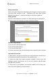
Software User Manual Safety Instructions Before using this FJDynamics Autosteering Kit (shorten as the kit), please read the entire contents of the “ FJDynamics AT2 Auto Steer System Software User Manual” carefully, and keep in mind when operate it. Safety Symbols After the control terminal is powered on, safety warnings are displayed on the home screen for 3 seconds, as shown in the figure below. Operator Requirements 1. Do not drive under the age of 18. 2. Do not drive after drinking. 3.
Software User Manual 4. When the kit is under the testing, calibration, adjustment, or automatic steering, please ensure that there are no people or obstacles near the running track to prevent personal injuries or property damages. Operation Rules 1. During driving or operating, it is strictly prohibited to get on or off the vehicle during driving. 2. The vehicle must be kept under monitoring by the driver to ensure timely intervention. 3.
Software User Manual Contents Chapter I About This Document ............................................................................ 1 1 Purpose ............................................................................................................... 1 Chapter II Product Overview ................................................................................... 1 1 Introduction .......................................................................................................
Software User Manual 3.2.6 Confirm Task Configuration .............................................. 42 4 Create Guidance Lines ................................................................................ 42 5 Start Operation.............................................................................................. 52 5.1 Operation Interface .......................................................................... 52 5.2 Operation Setting ............................................................
Software User Manual Chapter I About This Document 1 Purpose This document provides a brief description on how to use the FJDynamics autosteering kit for agricultural vehicles in a simple and clear way. Users can learn to perform each operation easily, quickly and accurately. 2 Technical Support Users can find the technical support and upgrade services provided by FJ Dynamics Technology Co., Ltd., once they purchased the product.
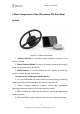
Software User Manual 2 Main Components of the FJDynamics AT2 Auto Steer System Figure 2.2.1 Main components 1. Control Terminal: To provide human-computer interaction and machine control. 2. Electric Steering Wheel: Consists of a steering motor and a steering wheel, to automatic steer the vehicle. 3. GNSS Receiver: To receive satellite and RTK signals to locate the vehicle and gain attitude information. Precautions for installing the GNSS receiver: 1.
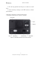
Software User Manual 5. The radio may generate heat during use, so watch out to avoid burns. 6. Avoid unnecessary coverings on the GNSS receiver to maintain good ventilation. 3 Hardware Interfaces of Control Terminal Figure 2.3.1 Hardware interfaces of the control terminal 3 ©FJ Dynamics Technology Co., Ltd. All rights reserved.
Software User Manual Chapter Ⅲ Software Operation Instructions of Control Terminal 1 Workflow Overview In order to facilitate the user's understanding of the operation and use of this kit, this manual will introduce the mainline use process of this product and related auxiliary functions from the perspective of a new user.
Software User Manual Figure 3.2.2 Selecting a language 2.2 Register/Login After completing the language settings, you will enter the registration and login screen. Account Registration: You are required to register an account for the initial use of the kit.Click Register immediately. On the displayed screen, enter your email address, verification code, and password, and click I agree in User Privacy Policy.
Software User Manual Figure 3.2.3 Home screen of login and registration 2.3 Entering Installation Information After successfully registering and logging in for the first time, you need to enter related installation information, user information and Auto Steer System information. Please note that the initial information you have entered will directly or indirectly affect your after-sales service.
Software User Manual The screen for entering agricultural vehicle information is displayed. Figure 3.2.5 Entering Auto-kit information Step 3:Specify all parameters about the agricultural vehicle and click Next step. Figure 3.2.6 Entering agricultural vehicle information After you select a type of the vehicle, the kit will directly enter the corresponding agricultural vehicle kit. Please select the type of the vehicle you will actually use. 7 ©FJ Dynamics Technology Co., Ltd. All rights reserved.
Software User Manual Figure 3.2.7 Selecting system mode Step 4: In terms of system mode, select the corresponding one. Please choose carefully according to the actual usage and click Save. The home screen is displayed. Fast mode The operation is simpler. The task can be started directly after importing the guidance line. Advanced mode Upgrade the field management function, start the operation after completing the task configuration, and have a more systematic management of the field data.
Software User Manual 2.4.1 Main Interface of Fast Mode Figure 3.2.8 The main interface of Fast Mode 1. Current driving mode:Shows the current driving mode, including manual driving mode and autosteering driving. 2. Wi-Fi signal: Show that the current device is connected to the wireless network. 3.Real-time speed: Displays the running speed of the current agricultural machine, and the speed unit can be changed in the setting. 4.
Software User Manual 9. Real-time video: Real-time monitoring of machine tool operation status through Wi-Fi camera, real-time feedback of operation status. (Note: Wi-Fi camera needs to be purchased separately.) 10.New Guidance line: Set new guidance line by clickping this shortcut button. 11. Autosteering Start / Stop button: Click to start or stop the vehicle. 12. Status: Click to access the real-time information and current status of agricultural machines. 13.
Software User Manual 1. Current driving mode:Shows the current driving mode, including manual driving mode and autosteering driving. 2. Wi-Fi signal: Show that the current device is connected to the wireless network. 3. Real-time speed: Displays the running speed of the current agricultural machine, and the speed unit can be changed in the setting. 4. 4G signal: The mobile network signals, shows the real-time cellular data communication of the autonomous driving system. 5.
Software User Manual 14. Vehicle: Shows the movement of vehicles in real-time. 15. Start task: After clicking, if the task configuration has been completed, it will enter the operation status; otherwise, it will enter the task configuration interface. 2.5 Select Correction Source You can connect to three correction sources: Mobile Base Station, Network RTK and SBAS. 1)Mobile Base Station: You need to select and power on a radio station, and pair with it.
Software User Manual Figure 3.2.10 Settings list Step 2: Select a correction source you want to use. On this screen, you can select to connect to a mobile base station, a network RTK, or SBAS. The kit connects to a mobile base station by default. You can change it through the toggle on the right. If you select Network RTK, this becomes the default mode next time you log in. Figure 3.2.
Software User Manual After switching on base station, go to Settings – Correction Signal Sources, and choose Mobile base station - Pairing via Code, and input the BS code in the prompt. Click OK after confirming the information is correct. Network RTK:To connect to the Network RTK, enable Network RTK and click Connect.In the displayed dialog box, enter your Ntrip domain name and account information. Ntrip domain: Enter the host and port, and click Get Source.
Software User Manual Figure 3.2.16 Connect to SBAS Figure 3.2.17 SBAS connected During SBAS connection, the Status is 1, and the operation cannot be started. After the connection is established, the Status becomes 2, and the source icon in the upper right corner changes to SXX. XX is the age of differential, which is a number from 0 to 20. 15 ©FJ Dynamics Technology Co., Ltd. All rights reserved.
Software User Manual Figure 3.2.18 Status after SBAS connection Note: 1. It takes up to 3 minutes to connect to a mobile base station or network RTK, and up to 5 minutes to connect to SBAS. 2. If connection to a correction source fails, try connecting to another correction source. If the fault persists, check the correction source in Settings > Troubleshooting, as shown below. Figure 3.2.19 Setting list 16 ©FJ Dynamics Technology Co., Ltd. All rights reserved.
Software User Manual The troubleshooting shows two results. The check mark indicates that the test is passed, and the cross mark indicates test failure. Figure 3.2.20 Troubleshooting 2.6 Setting Vehicle Parameters After entering the home screen of the kit, perform the following operations to set vehicle parameters: From the sidebar, choose Settings -> Vehicle Information. Figure 3.2.21 Setting List 17 ©FJ Dynamics Technology Co., Ltd. All rights reserved.
Software User Manual Figure 3.2.22 Vehicle information *For details about the measurement operations, please check the corresponding commissioning instruction video. 2.7 Calibrating Angle Sensor After completing vehicle parameter settings, you need to calibrate the angle sensor. Perform the following operations to calibrate the angle sensor: Step 1: Choose Settings -> Parameter Settings. Figure 3.2.23 Setting list 18 ©FJ Dynamics Technology Co., Ltd. All rights reserved.
Software User Manual Step 2: Click Angle Sensor Calibration in the detailed page of Parameter settings. Figure 3.2.24 angle sensor calibration Step 3: User needs to select the sensor type after getting into the angle sensor setting page. Figure 3.2.25 Select angle sensor type If the selected type is "Hall Sensor", then the user needs to select the installation position of the angle sensor. After selecting the installation location, click "Calibrate" to directly enter the calibration process.
Software User Manual follow the prompts in the following interface to calibrate. Rotate the steering wheel according to the process leftmost-rightmost-center and click OK after each action finished. Figure 3.2.26 Turning the wheel to the leftmost Figure 3.2.27 Turning the wheel to the rightmost 20 ©FJ Dynamics Technology Co., Ltd. All rights reserved.
Software User Manual Figure 3.2.28 Turning the wheel to the center If the angle sensor type is selected as Attitude sensor, please then select the installation position of your angle sensor. Note: when you choose Attitude sensor, you should drive straight for 1520m in manual mode to complete data convergence every time you open the system. Figure 3.2.29 attitude sensor If the angle sensor type is selected as No angle sensor, after selecting No angle sensor, enter its interface as shown below.
Software User Manual Figure 3.2.30 No angle sensor After entering the setting screen for no angle sensor, put the vehicle’s gear into the low gear first. Then, click Detect and step on the accelerator to make the agricultural vehicle run straight for about 20 m on a flat ground freely at a low speed (2–3 km/h) until the Detection Done prompt box is displayed. Then, the vehicle steering speed ratio is automatically detected and the setting of no angle sensor is completed. Figure 3.2.
Software User Manual Figure 3.2.32 Detect finished If the sensor type is switched, the device needs to be restarted after the sensor is switched to take effect. 2.8 Vehicle Calibration After angle sensor calibration finished, you need to calibrate vehicle to correct working offset. Perform the following operations to calibrate vehicle: Step 1: On the displayed Settings screen, click the Parameter Settings. Figure 3.2.33 Setting List 23 ©FJ Dynamics Technology Co., Ltd. All rights reserved.
Software User Manual Step 2: Click into Vehicle Calibration in the parameter page. Figure 3.2.34 Vehicle Calibration Step 3: Click Start Calibration in the vehicle calibration page, and then getting into the calibrating process. Figure 3.2.35 Start Calibration Step 4: On the calibration screen, carefully read the current calibration step displayed. Then, determine Points A and B exactly as prompted on the screen.
Software User Manual Figure 3.2.36 Confirm Point A Step 5: After confirming Point A, manually drive the vehicle straight for 50m and Confirm Point B. 6 Figure 3.2.37 Confirm Point B During the driving towards Point B, the distance traveled will be displayed on the upper right corner of the screen in real time. You can check whether the current distance from Point A meets the distance requirement of 50m based on this value.
Software User Manual 3 on the screen to manually turn the vehicle around and make it return to Point B on the guidance line just confirmed (with the front end of the vehicle facing Point A). After the adjustment is completed, click Start to make the vehicle run to Point A in the auto steering driving mode according to the guidance line just confirmed. Figure 3.2.38 Starting auto steering driving after turning around Step 7: Click Stop after the vehicle arrives at Point A in the autosteering driving mode.
Software User Manual Step 8: Manually turn the vehicle around to make it return to Point A on the guidance line (with the front end of the vehicle facing Point B). Then, click Start to make the vehicle run from Point A to Point B in the auto steering driving mode. Figure 3.2.40 Manually turning around and start the auto-working Step 9: After the vehicle reaches Point B in the auto steering driving mode, click Stop to stop the current auto steering driving operation. Figure 3.2.
Software User Manual calibration and return to the home screen. Figure 3.2.42 Calibration finished After completing the above steps of commissioning, you can start to use control terminal for intelligent operations. 3 Preparatory Operations 3.1 Preparatory Operation in Fast Mode Figure 3.3.1 Preparatory operation procedure 3.1.1 Confirm the Source Connection Confirm the source connection before operation preparation: (1) Check whether the source connection mode is correct.
Software User Manual Figure 3.3.2 Confirm the source connection mode (2) Check whether the connection is normal. If the Network RTK mode is used, RTK is displayed in the upper right corner; if the SBAS mode is used, SXX is displayed. Then, check whether you have full signal bars in the status bar. Figure 3.3.3 "RTK" displayed in the upper right corner when the RTK mode is used 29 ©FJ Dynamics Technology Co., Ltd. All rights reserved.
Software User Manual Figure 3.3.4 "SXX" displayed in the upper right corner when the SBAS mode is used 3.1.2 Getting the Heading Angle If the RTK connection is normal, drive ahead and accelerate the vehicle for more than 5s(Only one operation is required for each startup). 3.1.3 Adding New Guidance Line After confirming the connection to the RTK, you can start setting points.
Software User Manual Figure 3.3.5 Guidance line list If Multi Line Mode is needed, please enter into Settings -> Parameter Settings -> Working width Alerts to set the working width for the preparatory operation in multi line mode, as shown in the following figure. Figure 3.3.6 Setting the operating space 31 ©FJ Dynamics Technology Co., Ltd. All rights reserved.
Software User Manual Figure 3.3.7 Guidance line imported 3.2 Preparatory Operation for Advanced Mode Figure 3.3.8 Preparatory operation flow chart 3.2.1 Confirm the Source Connection Before preparing the operation, please confirm the current source connection. For the specific operation steps, see 2.5 Select Correction Source. If the RTK connection is normal, drive ahead and accelerate the vehicle for more than 5s(Only one operation is required for each startup). 3.2.
Software User Manual Figure 3.3.9 Task configuration entry The configuration field interface is shown in the figure below: Figure 3.3.10 Configure field interface 1. Task configuration items: Select the fields, boundaries, guidance lines and task settings required for the operation. Yellow represents the current configuration items. Under each item, it will display current selection. If it has not been selected, it will display not selected. Otherwise, the corresponding option is displayed below. 2.
Software User Manual 3. Field list: Display existing fields, including field name and creation time. Click to select the field to be operated. 4. Field basic information: Including field name, farm name, farm owner and creation time. 5. Field map: Display the current position and selected boundary and guidance line position. 6. Delete field: Click to delete the field, and the associated boundary, guidance line and history data will be simultaneously deleted and cannot be restored and cannot be restored. 7.
Software User Manual Figure 3.3.11 Interface for adding field 35 ©FJ Dynamics Technology Co., Ltd. All rights reserved.
Software User Manual 3.2.3 Add and Select Task Click Task Name to add or select from the list the intended task. The task selection interface is as follows: Figure 3.3.12 Setting Interface for Task Name 1. Task settings list: Task settings that has been created. 2. Task progress: Check the task progress. 3.
Software User Manual 3.2.4 Add and select boundary Click Boundary to add or select from the list the intended. If the operation does not require an boundary, select the No boundary option. The configuration boundary interface is shown in the figure below: Figure 3.3.13 Interface for configuring boundary 1. Boundary list: Display the existing boundary, including name of boundary, the operatable area enclosed and the creation time. 2.
Software User Manual Add boundary Press the Start button on the “Add boundary” interface. Figure 3.3.14 Interface of “Add Boundary” After pressing the Start button, you need to select the position of the implement to determine the position of the boundary, then click Confirm. Figure 3.3.15 Interface of boundary plan When finished, press the Pause button and choose Save. 38 ©FJ Dynamics Technology Co., Ltd. All rights reserved.
Software User Manual Figure 3.3.16 Interface when finished recording the boundary When saving, you need to fill in the boundary name, margin and the offset. During operation, a pop-up window will prompt when the distance from the field edge is 30m. Figure 3.3.17 Interface of saving the boundary When saving the boundary, if the boundary does not meet certain 39 ©FJ Dynamics Technology Co., Ltd. All rights reserved.
Software User Manual requirements, the following adjustments will be given for different situations: Table 3.3.1 Adjustments for irregular boundaries Boundary situation Adjustments Example Auto-completion of x<10m boundary xDistance between Connect with a 10m
Software User Manual No guideline. The guidance line configuration interface is shown in the figure below: Figure 3.3.18 Interface for configuring guidance line 1. The guidance line list of the field: Display the existing guidance lines, including the name, length and creation time of the guidance line. 2. List of guidance lines without attribution: Display the guidance lines generated in the extreme Fast Mode. 3.
Software User Manual 3.2.6 Confirm Task Configuration After all the information are selected, Click confirm button, and an information confirmation window will pop up. After confirming that the configuration information is correct, click OK. Click Start button on the homepage to enter the operation interface. Figure 3.3.19 Interface for confirming configuration 4 Create Guidance Lines The guidance line includes straight line mode (AB line mode), curve mode and pivot mode.
Software User Manual Figure 3.4.1 Adding new guidance lines in Fast Mode In Advanced Mode, click the Task in the sidebar column to expand the full interface for task settings. You may create new guidance lines on the interface of guidance line settings by clicking the Add button in the bottom column. Figure 3.4.2 Adding guidance lines in Advanced Mode Detailed steps for creating different guidance lines are shown below. Linear Mode 43 ©FJ Dynamics Technology Co., Ltd. All rights reserved.
Software User Manual Step 1: Move the vehicle to the starting point of the operation, and click Confirm Point A on the screen of control terminal to determine the current position as Point A of the new guidance line. After confirming Point A, manually drive the vehicle straight for 15–20m. Figure 3.4.3 Confirming Point A Step 2: Brake the vehicle and click Confirm Point B on the screen of the in-vehicle control terminal to determine the current position as Point B on the guidance line.
Software User Manual Figure 3.4.4 Confirming Point B Step 3: After confirming Point B, please click Import and enter the guidance line name in the prompt. Then go back to the list of guidance lines after naming the new line. And the newly added guidance line will be displayed on the top of the list. Figure 3.4.5 Import Guidance Line Curve Mode: 45 ©FJ Dynamics Technology Co., Ltd. All rights reserved.
Software User Manual Step 1: On the displayed Guidance Line setting page, click Straight Line to switch the plotting mode to the curve. Figure 3.4.6 Switch plotting mode to the curve Step 2: After switching to the curve mode, please move the vehicle to the starting point of the operation, and click Confirm Point A on the screen to confirm the current position as Point A on the curve guidance line. Figure 3.4.
Software User Manual path to the ending point of another side you want to determine (for example, from the starting point to the other field edge) in manual mode and click Confirm Point B. Figure 3.4.8 Confirming Point B Step 4: After confirming point B, please click Import and enter a new line’s name, and then you can get into the curve mode working page. Figure 3.4.9 Import new guidance line Notes for the curve mode: 1.
Software User Manual point on on the edge of the opposite side. 2. In multi-line mode, make sure to travel in the same line lengths as the curve guidance line, or the route beyond the curve guidance line will gradually tend to a straight line. 3. In curve mode, after confirming Point A, you cannot directly click Linear to switch to Straight line mode. Please cancel the point A before switching the mode.
Software User Manual Figure 3.4.11 Switch to Pivot Mode Step 2: Set point A at the starting point, drive the vehicle along the outer edge of the circular field for at least 20m, set point B and click Save. Figure 3.4.12 Set point A 49 ©FJ Dynamics Technology Co., Ltd. All rights reserved.
Software User Manual Figure 3.4.13 Set point B Step 4: Enter the distance from the edge of the implement to the edge of the field, click Confirm, enter the name of the guidance line and then save. Figure 3.4.14 Set field edge distance 50 ©FJ Dynamics Technology Co., Ltd. All rights reserved.
Software User Manual Figure 3.4.15 Interface of working with Pivot Mode Note: When working with Pivot Mode, and the vehicle is 20m away from the starting point, please follow the instructions in the notification to get prepared to disengage from auto mode and enter the next work path. Then, repeat the above operations until all paths are completed. Figure 3.4.16 Interface of auto-steering 51 ©FJ Dynamics Technology Co., Ltd. All rights reserved.
Software User Manual 5 Start Operation 5.1 Operation Interface The interface of Fast Mode Figure 3.5.1 Operation interface 1. Operation record button: Yellow means that the current operation data is recording. And white means that the current operation data is not recorded. Click to switch the recording status. 2. Auto-driving button: Yellow means it is in auto-driving status. White means it is not in auto-driving status. Click to switch driving status. 3.
Software User Manual 7. End task: Click to end the task.And users can view the details of this operation in the History data. The interface of Advanced Mode Figure 3.5.2 Interface of Advanced Mode 1. Real-time task information: On the bottom column you can see the serial number of the guidance line where the vehicle is currently located, the total area of the field, the area that has been worked, the proportion of the area that has been worked, and the real-time speed. 2.
Software User Manual mode and single line mode of guidance line. 6. Offset distance: The offset distance between the current path and the guidance line is displayed in real time, and the unit can be changed in the settings. 7. Guicance line: Guidance line for auto-steering 8. Boundary: The red one is the recorded boundary, and the black is the scaled boundary.
Software User Manual the user's actual operation needs, six operations can be carried out: switching operation record status, switching driving mode, shifting the guidance line, switching operation mode, marking the field and switching guidance lines and boundaries. The specific operation process is as follows: (1) Switch operation record status Click Record button in the lower left corner of the main interface to switch the status of the operation record.
Software User Manual Figure 3.5.3 Selecting Guidance Line Translation 1.Guidance Line Translation: Click Guidance Line Translation, and click Translate to the Current Position or Translate to the Fixed Position based on the operation. Translate to the Current Position: Click Translate to the Current Position and then click OK to translate the guidance line to the position of the agricultural machinery. 56 ©FJ Dynamics Technology Co., Ltd. All rights reserved.
Software User Manual Figure 3.5.4 Translate to the current position Translate to the Fixed Position: Click Guidance Line Translation, select the moving direction, enter the moving distance, and then click OK. Figure 3.5.5 Translate to the fixed position Note for The Use of Translating Guidance Line: Shift guidance line function is available only in the manual driving status in the multi-line mode. 57 ©FJ Dynamics Technology Co., Ltd. All rights reserved.
Software User Manual (4) Switch operation mode The operation mode is divided into single line mode and multi-line mode. The user can click multi line mode/single line mode in the operation setting to switch the current operation mode.
Software User Manual Figure 3.5.8 Single line mode (5) Mark the Edge Figure 3.5.9 Marking the field edge After importing guidance line or during the intelligent operation, you can enable the function of marking the field edge according to the actual needs. This function can alert the user when the vehicle is about to reach the field edge of another side, thereby effectively avoiding safety accidents especially in dark environment. 1.
Software User Manual if you want to use this function, drive the vehicle to the field edge and click Mark the Edge to mark the current position of the vehicle as the field edge. 2. The system will provide an alert sound and alert message for careful driving when the vehicle travels 30m away from the marked field edge. 3. When the system warns driver, you can click Pause to suspend the current autosteering driving and resume the manual driving mode.
Software User Manual Figure 3.5.10 A red dashed line that guides the tractor 5.3 Operation of Physical Key Module (Optional) The physical key module is an independent button panel module used in conjunction with FJDynamics autosteering system for agricultural vehicles. Some software functions can be controlled through the physical buttons to achieve more efficient system control in the autosteering mode.
Software User Manual Figure 3.6.1 Advanced functions 2. Enter the activation code in the pop-up dialog, and click OK. Figure 3.6.2 Enter the activation code 3. After the activation code is verified, an Information Confirmation dialog pops up. Click Activate to activate the function. 4. After the function is activated, you can view its status and remaining valid time on the Advanced Functions screen. Click the function to enter the screen of function details to enable or disable the function.
Software User Manual Figure 3.6.3 Advanced functions Uturn: Automatically plans paths at any position in the field for automatic Uturns and headland operations. Applicable field types: 1. Rectangle or approximate rectangle fields Figure 3.6.4 Rectangle or approximate rectangle fields 2. Quadrilateral fields with large included angles Figure 3.6.5 Quadrilateral fields with large included angles 3. Approximate quadrilateral fields with small missing parts 63 ©FJ Dynamics Technology Co., Ltd.
Software User Manual Figure 3.6.6 Approximate quadrilateral fields with small missing parts Shapes of fields that can be partially planned: 1. Quadrilaterals with large missing parts 2. Polygons, triangles, teardrops, and other shapes with large triangular space Figure 3.6.7 Shapes of fields that can be partially planned Fields that cannot be planned: 1. Overly narrow fields 2. Overly small fields Figure 3.6.8 Fields that cannot be planned The operation procedure is as follows: 1.
Software User Manual Information. Ensure that the turning radius is correct. To get the turning radius, drive the vehicle to make a circle by turning the steering wheel to full lock and measure the radius of the outer ring that the vehicle leaves on the ground. Figure 3.6.9 Set the turning radius Figure 3.6.10 Set the implement parameters 2.Choose Settings > Advanced functions > Uturn, and enable or 65 ©FJ Dynamics Technology Co., Ltd. All rights reserved.
Software User Manual disable the function. Figure 3.6.11 Uturn details 3.Click Task and choose the field, boundary, and guidance line. If you select No guideline, the guidance line will be generated automatically when the Uturn function is enabled. 66 ©FJ Dynamics Technology Co., Ltd. All rights reserved.
Software User Manual Figure 3.6.12 Choose the boundary and the guidance line when creating an operation 4.Click Start, drive the vehicle to the Uturn start point, and click the Uturn icon on the right. Figure 3.6.13 Operation screen Note: If No guideline is selected, the pop-up dialog "There is no guidance line, whether to generate it automatically?" appears. Click OK and select the direction to generate the guidance line. Figure 3.6.14 Pop-up dialog displayed when No guideline is selected 5.
Software User Manual performs it based on the boundary shape. Figure 3.6.15 Automatic headland operation when you choose to perform it If you choose not to perform the headland operation, the system recommends the optimal headland path when autosteering is completed. You need to manually drive the vehicle to the start point of the recommended headland path. Figure 3.6.16 Optimal headland path recommended when you choose not to perform the headland operation 6.
Software User Manual Figure 3.6.17 Uturn coverage 7.Follow the green line to drive to the start point, and click Start. Figure 3.6.18 Start the Uturn task Note: Before confirming the Uturn settings, ensure that your vehicle is close to the start point, and heading to the working direction of a guidance line. If the vehicle deviates from the guidance line with a large angle, the 69 ©FJ Dynamics Technology Co., Ltd. All rights reserved.
Software User Manual Uturn operation cannot be started. If the Uturn operation cannot be started when the vehicle is aligned to the guidance line, the vehicle might be heading to the opposite direction. Fault prevention: Scenario 1 When the user exits the task and enters it again without changing any parameters: The original paths will be kept.
Software User Manual Users click the Status to access the working status and operation of the vehicle.
Software User Manual 7.2 Location History Figure 3.7.2 Operation Data 1. Check the operation list. After expanding the operation data details page, users can view the single information of historical operations here, including: operation time, operation width, operation area, operation efficiency etc. 2. Filter the job list. Users can filter the operation information by month. After the data is filled in, click Filtering to refresh the list. 3. Filter the operation list.
Software User Manual date of the last job operation. 4. The acre and time are cumulative items of historical operations instead of a single data of the latest operation. 7.3 Settings Figure 3.7.3 Setting list The user clicks Setting to expand the setting details page and display the setting items. 7.3.1 Working Width Alerts 73 ©FJ Dynamics Technology Co., Ltd. All rights reserved.
Software User Manual Figure 3.7.4 Working width alerts On the displayed Parameter Settings screen, click the Working Width Alerts tab. The displayed details screen allows setting Operating space, Speed Alert and Offset Range Alert. Click the item that needs to be set and enter the corresponding value. Operating spacing: indicates the distance between adjacent guidance lines in multi line mode. Speed alert: indicates the warning speed preset.
Software User Manual Figure 3.7.5 NMEA settings Data Transfer Map information, including field, boundary, guidance line, and task data, can be exported out of or into the FJD autosteering kit through online sharing or USB flash drive. Online Sharing: Before the USB flash drive is inserted, data can be transferred to the designated user through online sharing.
Software User Manual Figure 3.7.7 Enter the account of designated user Step 3: Select the current device SN and click OK. A window pops up if the sharing is successful. Figure 3.7.8 Select the device SN USB flash drive: Step 1: Insert the mobile storage device into the T1 port above the vehicle display control terminal (the T1 port is a USB Type-C port, if the mobile storage device is a Type-A port, it is required to purchase a 76 ©FJ Dynamics Technology Co., Ltd. All rights reserved.
Software User Manual connector converter). Figure 3.7.9 Connection diagram of mobile storage device Step 2: Enter the data transfer interface, user can export map information via USB, such as: fields, boundary, guidance line, mission data etc..For use by other terminals, and users can also import map information from other devices to FJDynamics Autosteering kit. Data information in some formats may not be imported. For details, refer to the description of the importable format displayed in the interface.
Software User Manual Notes: 1.Only data in the formats specified on the screen can be imported. 2.Before inserting the USB flash drive, you can share the boundary and guidance line online. After the USB flash drive is inserted, online sharing is not supported. 3.Task data cannot be shared online. Terrain Compensation If the operation field contains more slopes, the terrain compensation can be turned on to achieve a more precise navigation effect.
Software User Manual Radar Output Module is also applicable to old version implements that support radar speed input, such as sprayers, spreaders, and seeders. You can purchase Radar Output Module separately according to your needs. 7.3.3 Vehicle Parameters Figure 3.7.11 Vehicle parameter settings Click the Vehicle Parameters tab. On the displayed details screen, click the required items and enter the corresponding vehicle data to complete vehicle parameter settings.
Software User Manual Figure 3.7.12 GNSS Receiver Offset Calibration Step 1: Create a guidance line: create and import a guidance line. (The starting point is point A, the end point is point B) Step 2: Set the line spacing and select the operation mode: set the operation spacing in the Parameter Setting to 10 meters, and select the operation mode as multi line mode. Step 3: Drive two times. First driving: Drive the vehicle at a low speed from point A to point B.
Software User Manual Step 5: Please enter a value in the interface of Positioning AntennaCentral Axis Distance, and click OK to complete the corresponding GNSS Receiver Offset Calibration. 7.3.4 Parameter Setting Choose Settings -> Parameter Settings. On the displayed screen, you can set Angle Sensor, Vehicle Calibration and Calibration of Accessories to ensure operational accuracy. Angle Sensor Figure 3.7.13 Angle sensor settings Click the Angle Sensor Calibration tab in Parameter Calibration page.
Software User Manual Figure 3.7.14 Settings for no angle sensor Calibration of Accessories Figure 3.7.15 Settings for calibration of accessories When auto-driving path has a offset within 3 cm after the implement is equipped, please measure the value.
Software User Manual OK. Parameters Commissioning (for FAE Only) Figure 3.7.16 Parameter settings Approach Aggressiveness: affects the time for the vehicle to enter the next guidance line when making a turn. The larger the value is, the shorter adjustment time the process needs. However, the driving instability is higher. Online Aggressiveness: affects the Straight line driving accuracy of the vehicle.
Software User Manual Vehicle Calibration Figure 3.7.17 Vehicle calibration For detailed operations, see section 2.8 Vehicle Calibration in Chapter IV Software Operation Instructions of In-vehicle Control Terminal. 7.3.5 Implement Information Click Implement Information in Settings to view the implement parameters and list of implements. Click Implement Parameters to view the way of implement connection, the distance between the implement and the hitch, and implement working parameters.
Software User Manual Figure 3.7.18 Implement parameter Click List of Implements and delete, edit, create, upload, and synchronize implements to create and manage the implement library. Note: The implement library can contain a maximum of 10 implements. Figure 3.7.19 List of implements Delete the Implement: Select an implement and click Delete to delete the implement information. 85 ©FJ Dynamics Technology Co., Ltd. All rights reserved.
Software User Manual Figure 3.7.20 Delete an implement Edit the Implement: Select an implement and click Edit to modify the implement information. Figure 3.7.21 Edit an implement Create New Implements: Click New and then perform the following steps: 86 ©FJ Dynamics Technology Co., Ltd. All rights reserved.
Software User Manual Step 1: Fill in the basic information of the new implement and click Next. Figure 3.7.22 Create new implements - basic information Step 2: Fill in the working information of the new implement, and click Save. If any item is not set, the information cannot be saved. Figure 3.7.23 Create new implements - work information 87 ©FJ Dynamics Technology Co., Ltd. All rights reserved.
Software User Manual Upload the Implement: Click the upload icon to upload implement information. Figure 3.7.24 Upload implements Synchronize the Implement: Click the synchronize icon to synchronize the previously uploaded implement information. Figure 3.7.25 Synchronize implement 88 ©FJ Dynamics Technology Co., Ltd. All rights reserved.
Software User Manual 7.3.6 System Settings System version (OTA upgrade) Figure 3.7.26 OTA Upgrade When there is an update to the software version, you can perform the following operations to achieve a one-click upgrade of the auto steering kit: 1. Turn on the in-vehicle control terminal of the autosteering kit. Make sure that the control terminal can access the Internet through network SIM card/Wi-Fi network and that the network status is stable (please make sure the 4G antenna is connected properly).
Software User Manual version. 6. If the upgrade fails, the system will prompt you to retry.Click Retry to re-upgrade the system. Notes for OTA upgrade: 1. Ensure that the network status is stable throughout the upgrade process. 2. Do not power off the terminal during the upgrade process. 3. If you encounter any problems during the upgrade, please contact your local dealer for help or call the technical service hotline. Mode selection User can switch between Fast Mode and Advanced Mode here.
Software User Manual Figure 3.7.27 Language selection 7.3.7 Wi-Fi Camera (Optional) Two Wi-Fi cameras can be connected via hotspot. The operation is as follows: 1. For the first use, please turn on the Wi-Fi camera in the Settings. 2. Turn on the hotspot mode before binding, and scan the code via camera to identify and bind the camera. Up to two cameras can be bound via scanning the code. The scanned camera is displayed on the right side. Click OK to enter the camera view page. 3.
Software User Manual Figure 3.7.28 Wi-Fi camera configuration 4. After the binding is completed, user can click return button in the upper left corner to enter the working interface, and Click real-time video button to open the main interface display. Figure 3.7.29 Real-time video 5. Click “Switch” button to switch the camera.Click “Full Screen” button to maximize the camera interface, and click again to restore. Click “Close” to close the camera window in a real time manner.
Software User Manual 7.3.8 Remote Commissioning Turn on the remote commissioning function, which should use with the background control program to realize the remote control screen function; user should turn on the Remote Debugging switch in the Settings. Figure 3.7.30 Remote commissioning 7.3.9 Changing the Password In Settings > User Information > Account and security, you can perform the following steps to change the password. 1.
Software User Manual Figure 3.7.31 User information 2. You will be logged out after the password is changed. You may log in again on the login screen displayed. Figure 3.7.32 Login 7.3.10 Other Settings In addition to Parameter Settings, Correction Source, and Troubleshooting, the Settings screen allows setting and querying other general information such as Volume, Brightness, and device information. 94 ©FJ Dynamics Technology Co., Ltd. All rights reserved.
Software User Manual Chapter Ⅳ FCC Warning NOTE: This equipment has been tested and found to comply with the limits for a Class B digital device, pursuant to part 15 of the FCC Rules. These limits are designed to provide reasonable protection against harmful interference in a residential installation. This equipment generates uses and can radiate radio frequency energy and, if not installed and used in accordance with the instructions, may cause harmful interference to radio communications.
Software User Manual Chapter Ⅴ FAQs No. Fault Troubleshooting 1 S turn in Check whether the rolling angle and pitching autosteering angle change in real time. operations Calibrate the angle sensor (optional). Check whether the GNSS receiver is installed and connected properly. 2 Steering wheel Check the brake. malfunction during Test the motor. autosteering Power off and restart the vehicle. operations Check whether the GNSS receiver is installed and connected properly.
Software User Manual and restart the vehicle” appeared during start-up 7 Slight offset in Check whether the rolling angle changes. straight line mode Chapter Ⅵ Main Hardware and its Specifications 1 Specification Table 1 No. Assembly Component Specifications Size: 275×180×40 mm; Basic configuration: 10.
Software User Manual Relative humidity: 0% - 95%, 40°C (non-condensation); Wi-Fi specifications: 2.4 GHz frequency band, BT 5.0 Frequency range: 2,412 – 2,462 MHz Radio communication: 900M/None Frequency range: GPS L1C/A、 L1C、L2P(W)、L2C、L5; GLONASS L1、L2;BDS B1I、 B2I、B3I、B1C、B2a;Galileo E1、E5a、E5b;SBAS; 2 GNSS Receiver GNSS Receiver Operating voltage: 9 V – 36 V; Operating current: < 300 mA; Size: 162x64.
Software User Manual ©FJ Dynamics Technology Co., Ltd. All rights reserved. ©FJ Dynamics Technology Co., Ltd. All rights reserved.